
Drum structure and compressor rotor wheel disc connection structure thereof

A technology of compressor rotor and connection structure, applied in mechanical equipment, machine/engine, liquid fuel engine, etc., can solve the problems of limiting the performance and damage of the compressor rotor system, and achieve guaranteed performance, avoid damage, and large-strength reserve. Effect

Active Publication Date: 2020-08-25
AECC SHENYANG ENGINE RES INST
View PDF8 Cites 0 Cited by
  • Summary
  • Abstract
  • Description
  • Claims
  • Application Information

AI Technical Summary

Problems solved by technology

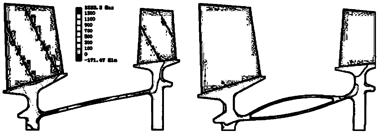
[0002] Compressors are the main components of aero-engines and gas turbines. The adjacent two-stage rotor disks are mostly connected by drums. The existing drums are mostly single-layer structures, and their strength reserves, especially circumferential stress reserves, are limited by current materials. It is difficult to adapt to the high-speed and high-temperature working environment of the current compressor rotor system, which limits the improvement of the performance of the compressor rotor system. In severe cases, it will be damaged, leading to catastrophic consequences

Method used


Image

  • Drum structure and compressor rotor wheel disc connection structure thereof
  • Drum structure and compressor rotor wheel disc connection structure thereof

Examples


Embodiment Construction

[0028] In order to make the technical solution of the present application and its advantages clearer, the technical solution of the present application will be further clearly and completely described in detail below in conjunction with the accompanying drawings. It can be understood that the specific embodiments described here are only part of the application Examples are only used to explain the present application, not to limit the present application. It should be noted that, for the convenience of description, only the parts related to the present application are shown in the drawings, and other relevant parts can refer to the general design. In the case of no conflict, the embodiments in the application and the technologies in the embodiments Features can be combined with each other to obtain new embodiments.

[0029] In addition, unless otherwise defined, the technical terms or scientific terms used in the description of the application shall have the usual meanings und...


PUM


Abstract

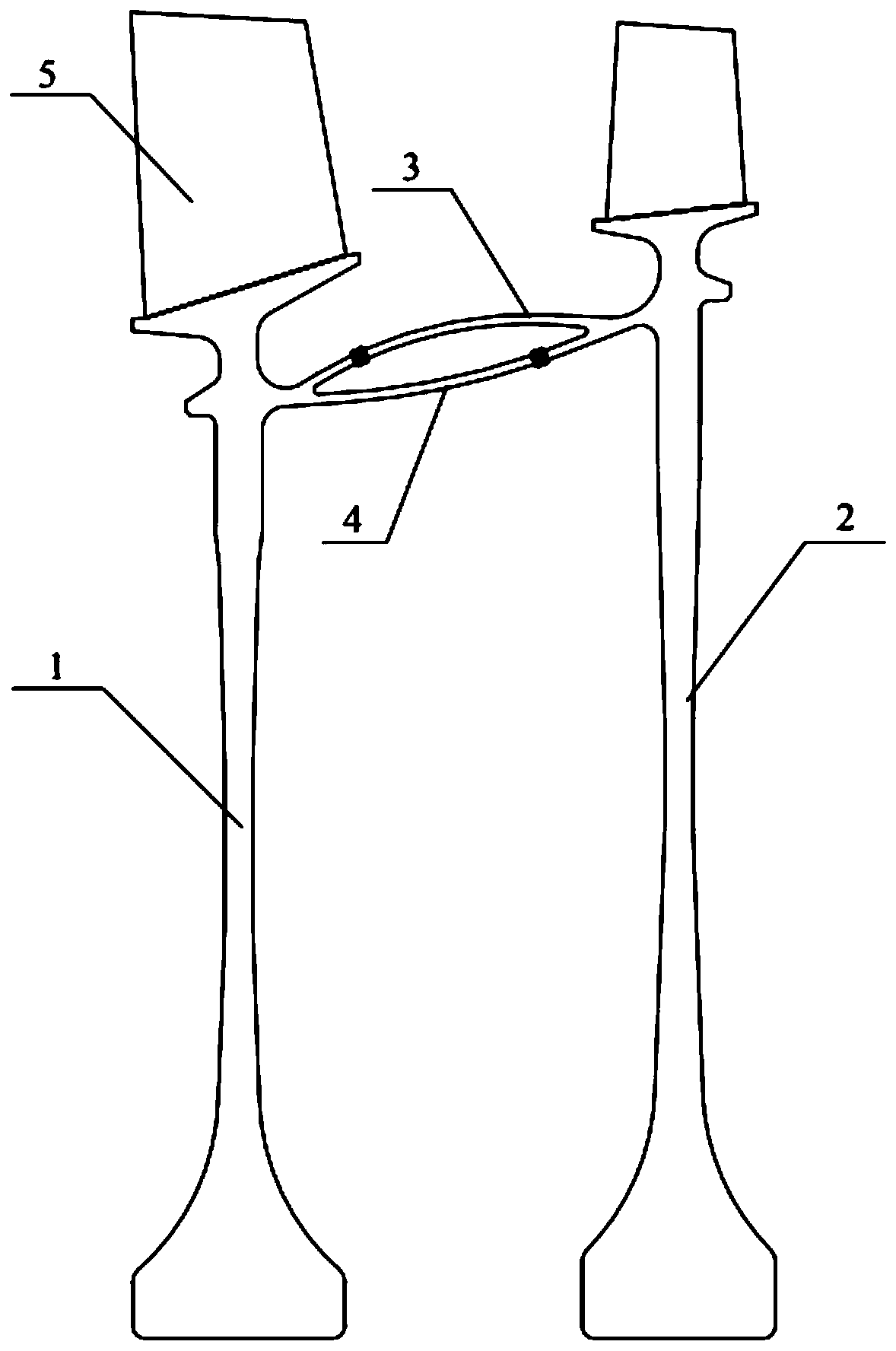
The invention belongs to the technical field of compressor rotor wheel disc connection design, and specifically relates to a compressor rotor wheel disc connection structure. The compressor rotor wheel disc connection structure comprises a front-stage rotor wheel disc, a rear-stage rotor wheel disc, an outer drum and an inner drum, wherein the rear-stage rotor wheel disc is adjacent to the front-stage rotor wheel disc, the outer drum is arranged between the front-stage rotor wheel disc and the rear-stage rotor wheel disc, one end of the outer drum is connected with the front-stage rotor wheeldisc, and the other end of the outer drum is connected with the rear-stage rotor wheel disc; and the inner drum is located on the inner side of the outer drum, one end of the inner drum is connected with the front-stage rotor wheel disc, and the other end of the inner drum is connected with the rear-stage rotor wheel disc. In addition, the invention relates to a drum structure including the outerdrum and the inner drum in the compressor rotor wheel disc connection structure.

Description

technical field [0001] The application belongs to the technical field of connection design of compressor rotor discs, and in particular relates to a drum structure and a compressor rotor disc connection structure thereof. Background technique [0002] Compressors are the main components of aero-engines and gas turbines. The adjacent two-stage rotor disks are mostly connected by drums. The existing drums are mostly single-layer structures, and their strength reserves, especially circumferential stress reserves, are limited by current materials. It is difficult to adapt to the high-speed, high-temperature working environment of the current compressor rotor system, which limits the improvement of the performance of the compressor rotor system. In severe cases, it will be damaged, leading to catastrophic consequences. [0003] In view of the existence of above-mentioned technical defect, propose this application. [0004] It should be noted that the disclosure of the above back...

Claims


Application Information

Patent Timeline
Patent Type & Authority Applications(China)
IPC IPC(8): F04D29/26
CPCF04D29/26F05D2220/3216
Inventor 张鑫印雪梅赵晓东
Owner AECC SHENYANG ENGINE RES INST
Learn More