
Stator of a rotating electrical machine

A technology for rotating electrical machines and stators, which is applied in the direction of electromechanical devices, electrical components, electric components, etc., and can solve problems such as poor iron loss, unsuitable suppression of out-of-plane deformation of the iron core, and high magnetic flux density of the iron core.

Active Publication Date: 2022-03-08
MITSUBISHI ELECTRIC CORP
View PDF12 Cites 0 Cited by
  • Summary
  • Abstract
  • Description
  • Claims
  • Application Information

AI Technical Summary

Problems solved by technology

[0007] When the iron core deforms out of plane, the magnetic flux that should have interlinked at the deformed portion flows to the surrounding iron core, which increases the magnetic flux density of the iron core around the deformed portion, resulting in a decrease in motor efficiency
In addition, when the iron core is plastically deformed due to out-of-plane deformation, the iron loss will deteriorate
[0008] In addition, the rivets are set so as to plastically deform the iron core, so if the number of rivets increases, the iron loss will worsen, resulting in a decrease in motor efficiency
[0009] In the example of Patent Document 1, when the shape of the frame maintains the same cross-sectional shape in the axial direction, and the stress on the laminated iron core embedded in the inner diameter side of the frame is uniform in the axial direction, by limiting the The two axial ends of the core are provided with riveting parts to suppress the out-of-plane deformation of the core, but the shape of the frame is not formed to maintain the same cross-sectional shape in the axial direction, and the stress on the laminated core is in the axial direction. Depending on the shape of the frame, simply providing rivets at both ends of the laminated core in the axial direction is not suitable for suppressing out-of-plane deformation of the core.

Method used


Image

  • Stator of a rotating electrical machine
  • Stator of a rotating electrical machine
  • Stator of a rotating electrical machine

Examples


Embodiment approach 1

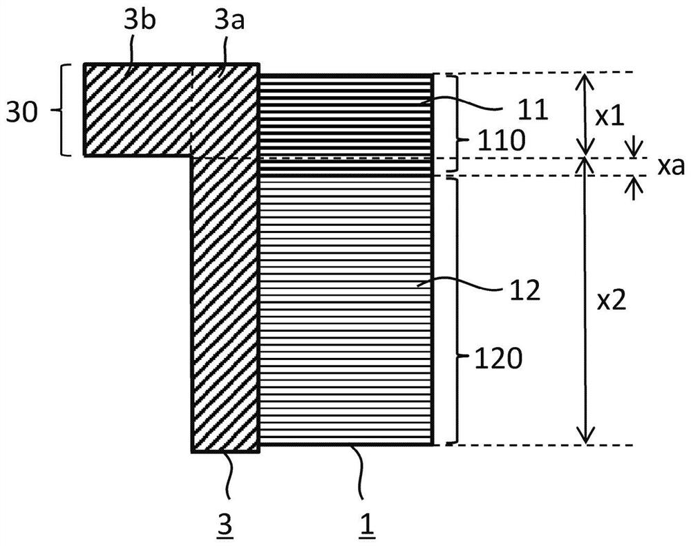
[0028] use Figure 1 to Figure 6 The stator 100 of the rotating electrical machine according to Embodiment 1 of the present application will be described. Additionally, use Figure 12 It is an explanatory diagram showing the state of the laminated iron core.

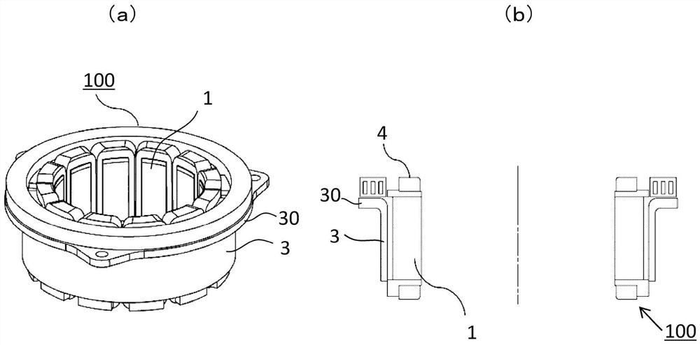
[0029] figure 1 (a) is a perspective view showing the stator 100 according to Embodiment 1, figure 1 (b) is along figure 1 Axial sectional view of the stator 100 of (a). As shown in these figures, the stator 100 is configured by inserting the laminated core 1 around which the coil 4 is wound, on the inner diameter side of the frame 3 extending in the axial direction in a cylindrical shape. In addition, the frame 3 has a frame high-rigidity portion 30 extending radially outward in a partial area in the axial direction, for example, an upper end side. The frame 3 may change its cross-sectional shape along the axial direction, and the cross-sectional area may change according to the change of the cross-sectional shape...

Embodiment approach 2

[0059] Next, refer to Figure 7 and Figure 8 Embodiment 2 of the present application will be described. In the above-mentioned example of Embodiment 1, the case where the frame 3 has the same shape in the circumferential direction has been described, but in this Embodiment 2, the following case will be described: Figure 7 As shown in the cross-sectional view of the main part of the stator 100, the frame cylindrical portion 3a is not simply cylindrical. The notch 31 penetrating the frame cylindrical portion 3 a is arranged in a notch forming region 31 a which is an intermediate position in the axial direction of the frame 3 .

[0060] Figure 8 (a), (b), (c) are along with Figure 7 The cross-sectional views of the frame 3 on the B1-B1 line, B2-B2 line, and B3-B3 line, which are perpendicular to the axial direction, respectively represent the area where the frame extension 3b is provided, the slot forming area 31a where the slot 31 is provided, The cross-sectional struct...

Embodiment approach 3

[0068] Next, Embodiment 3 of the present application will be described. In this embodiment 3, use Figure 9 and Figure 10 Modifications of the first core 11 and the second core 12 will be described.

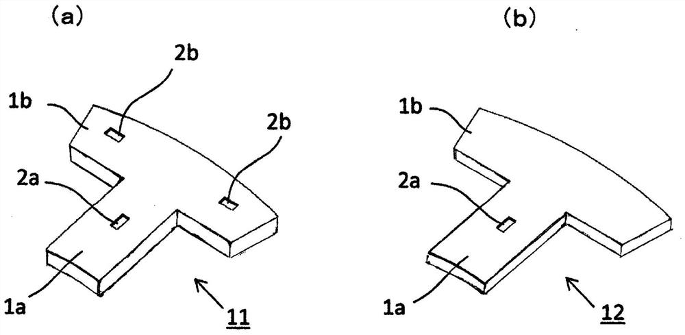
[0069] As described above, the first iron core 11 and the second iron core 12 are divided into the pole tooth portion 1a on which the wire is wound and the iron core back 1b forming a ring in the circumferential direction, and the riveting 2a and the riveting 2b are all provided. On the core back 1b.

[0070] Figure 9 (a) is a top view of the first iron core 11 as an example, and shows the riveting 2a provided on the entire length of the laminated iron core 1 in the axial direction and the riveting 2b additionally provided to strengthen the fastening force between the cores. In the state where one layer of first iron cores 11 is provided, at the center of the core back 1b in the circumferential direction, a riveting member 2a is provided on the inner side in the radial dire...


PUM


Abstract

In the structure in which the laminated iron core (1) is embedded and fixed in the frame (3), the frame (3) has a portion composed of only the frame cylindrical portion (3a) having a predetermined thickness in the axial direction and includes In the case of the frame high rigidity part (30) of the frame extension part (3b) in which the outer peripheral part of the frame cylindrical part (3a) protrudes outward, the frame cylindrical part fixed in the laminated iron core (1) On the inner diameter side of (3a), the second iron core (12) provided with riveting parts (2a) arranged on the entire length of the laminated iron core (1) is fixed on the inner diameter side of the high rigidity part (30) of the frame The first iron core (11) is not only provided with the riveting part (2a) but also additionally provided with the riveting part (2b), and the number of riveting parts is increased only in necessary parts.

Description

technical field [0001] This application relates to stators for rotating electric machines. Background technique [0002] Against the background of global warming, in order to reduce carbon dioxide emissions of automobiles, it is required to improve fuel efficiency, or to promote electrification of automobiles equipped with motors. [0003] Furthermore, in order to improve fuel efficiency, higher output of motors is required. Generally, a laminated core made of laminated steel plates is used for a stator of a motor, and riveting is provided on the laminated core in order to fix the laminated steel plates to each other. [0004] In addition, as a prior art, there is disclosed a technique in which, for a laminated iron core embedded in a frame having the same cross-sectional shape continuous in the axial direction, riveting members are provided at both ends in the axial direction of the laminated iron core. The stacked iron cores are fixed in the axial direction by a rivet (f...

Claims


Application Information

Patent Timeline
Patent Type & Authority Patents(China)
IPC IPC(8): H02K1/18
CPCH02K1/187
Inventor 木虎竜一中野正嗣古西启一菅野千秋大桥直树
Owner MITSUBISHI ELECTRIC CORP
Learn More