
Energy-dissipating joint assembly and earthquake-resistant structure using the same

A technology for joining components and structures, used in earthquake-proof, bridge parts, building components, etc., can solve problems such as structural fractures, huge property losses, and severe structural disasters, and achieve the effect of suppressing out-of-plane deformation

Active Publication Date: 2017-07-14
CHINA STEEL
View PDF5 Cites 0 Cited by
  • Summary
  • Abstract
  • Description
  • Claims
  • Application Information

AI Technical Summary

Problems solved by technology

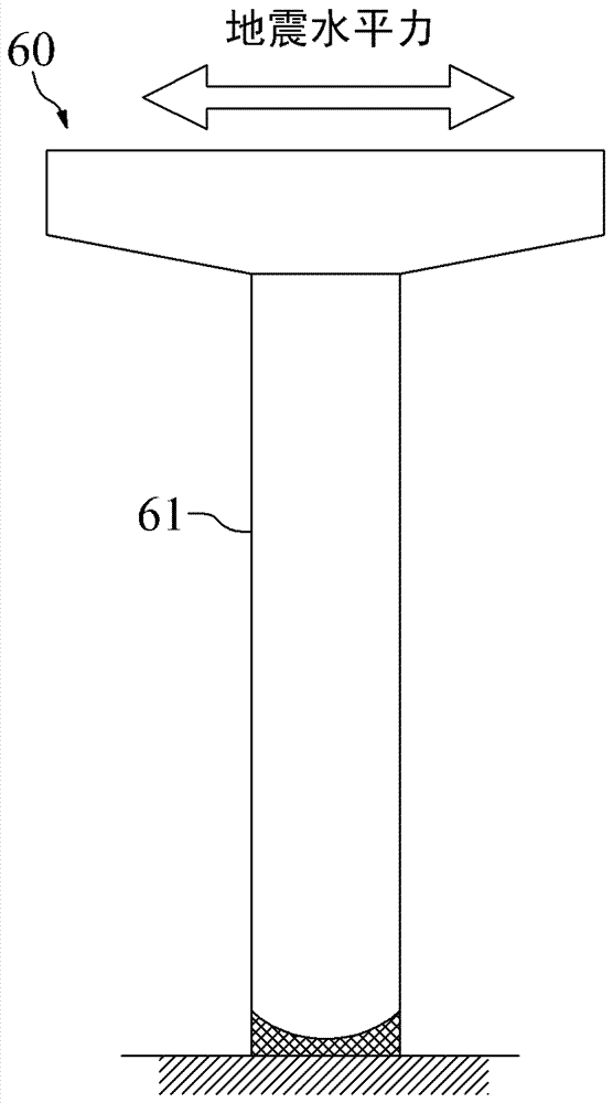
Cooperate with reference figure 1 and figure 2 , when the known steel bridge column (beam) structure 60 is subjected to the earthquake horizontal force, the maximum acting bending moment will be generated at the bottom of the steel bridge column 61, thereby causing the steel bridge column 61 to produce deflection deformation and local buckling, As a result, the steel bridge column 61 breaks, and the anchorage of the steel bridge column 61 is buried deep in the ground, so it is difficult to detect its damage after the earthquake
In addition, the steel bridge column 61 can only produce a traditional plastic hinge in mechanics under ideal conditions, so the earthquake resistance is also limited
[0004] In addition, the known cause of damage to building steel structures is often that the earthquake force will be concentrated in the beam-column joint area, so that the structure breaks or collapses
[0005] Since the damage of the above-mentioned structures may cause serious disasters and huge property losses, it is necessary to provide an innovative and progressive energy-dissipating joint component and a shock-resistant structure to solve the above-mentioned problems

Method used


Image

  • Energy-dissipating joint assembly and earthquake-resistant structure using the same
  • Energy-dissipating joint assembly and earthquake-resistant structure using the same
  • Energy-dissipating joint assembly and earthquake-resistant structure using the same

Examples


Embodiment Construction

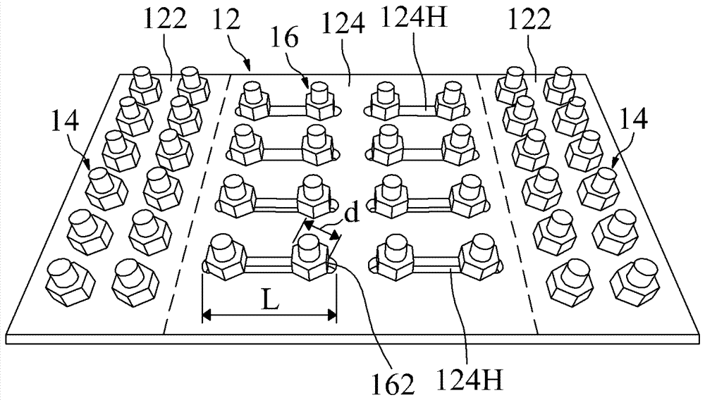
[0022] image 3 A three-dimensional combined view showing the energy dissipation joint assembly according to the first embodiment of the present invention. Figure 4 A top view showing the structure of the joint plate according to the first embodiment of the present invention. Figure 5 A schematic diagram showing the energy-dissipating joint assembly of the first embodiment of the present invention jointed with a structural body. Cooperate with reference image 3 , Figure 4 and Figure 5 The first energy-dissipating joint assembly 10 according to the first embodiment of the present invention includes a first joint plate 12 , a plurality of first joint bolts 14 and a plurality of first bolts 16 .

[0023] The first joint plate 12 has two first joint sections 122 and a first energy dissipation section 124 . The two first joining sections 122 are used to join a first structural body 50, and the first structural body 50 may be selected from one of the following: steel girde...


PUM


Abstract

The invention relates to an energy-dissipating joint assembly and an anti-seismic structure using the same. The energy-dissipating joint assembly includes: a joint plate having two joint sections and an energy-dissipating section, the two joint sections are used to join a structural body, the energy-dissipating section is located between the two joint sections, and The energy dissipation section has a plurality of slots, each of which has a length and a width; and a plurality of bolts, the steel plates in the energy dissipation area are provided with slots, and the slots are equipped with bolts, and the bolts are used to bind The steel plate is deformed outside the plane, and the bolts in the slots can slide on the plane of the steel plate. The two end regions of the energy dissipation section are firmly joined with the structural body. Each of the bolts has a head, and the outer diameter of each head is smaller than the length of each of the slots, but larger than the width of each of the slots. The invention can convert the external force acting on the structure body into more uniform tension and pressure in the energy dissipation area, so as to avoid stress concentration and destroy the structure body.

Description

technical field [0001] The invention relates to an energy-dissipating and shock-resistant structure, in particular to an energy-dissipating joint assembly and a shock-resistant structure using the same. Background technique [0002] Known architectural steel structures or steel bridge column (beam) structures are often damaged or collapsed by earthquakes or typhoons, and are very difficult to repair. [0003] figure 1 A schematic diagram showing a known steel bridge column (beam) structure subjected to an earthquake horizontal force. figure 2 The bending moment diagram of known steel bridge column (beam) structure subjected to seismic horizontal force is shown. Cooperate with reference figure 1 and figure 2 , when the known steel bridge column (beam) structure 60 is subjected to the seismic horizontal force, the maximum acting bending moment will be generated at the bottom of the steel bridge column 61, thereby causing the steel bridge column 61 to produce deflection d...

Claims


Application Information

Patent Timeline
Patent Type & Authority Patents(China)
IPC IPC(8): E01D19/00E04B1/98
Inventor 黄庆渊陈生金
Owner CHINA STEEL
Learn More