
Anti-shock fire-fighting lance

A water gun and firefighting technology, applied in fire rescue and other directions, can solve the problems of property loss, high water pressure, labor and other problems, and achieve the effect of increasing the coverage area of ​​water flow and improving the efficiency of fire extinguishing.

Active Publication Date: 2020-08-28
辽宁众成消防工程有限公司
View PDF5 Cites 0 Cited by
  • Summary
  • Abstract
  • Description
  • Claims
  • Application Information

AI Technical Summary

Problems solved by technology

[0003] Because the high-pressure sprayed water flow of the fire water gun is often in the shape of a straight water column, and the water pressure is high, so that it is too laborious to turn and spray. If the flame distribution area is large, the water column will not be able to quickly extinguish the large-area flame. lead to greater property damage

Method used


Image

  • Anti-shock fire-fighting lance
  • Anti-shock fire-fighting lance
  • Anti-shock fire-fighting lance

Examples


Embodiment 1

[0025] For example figure 1 -example Figure 4 Shown:

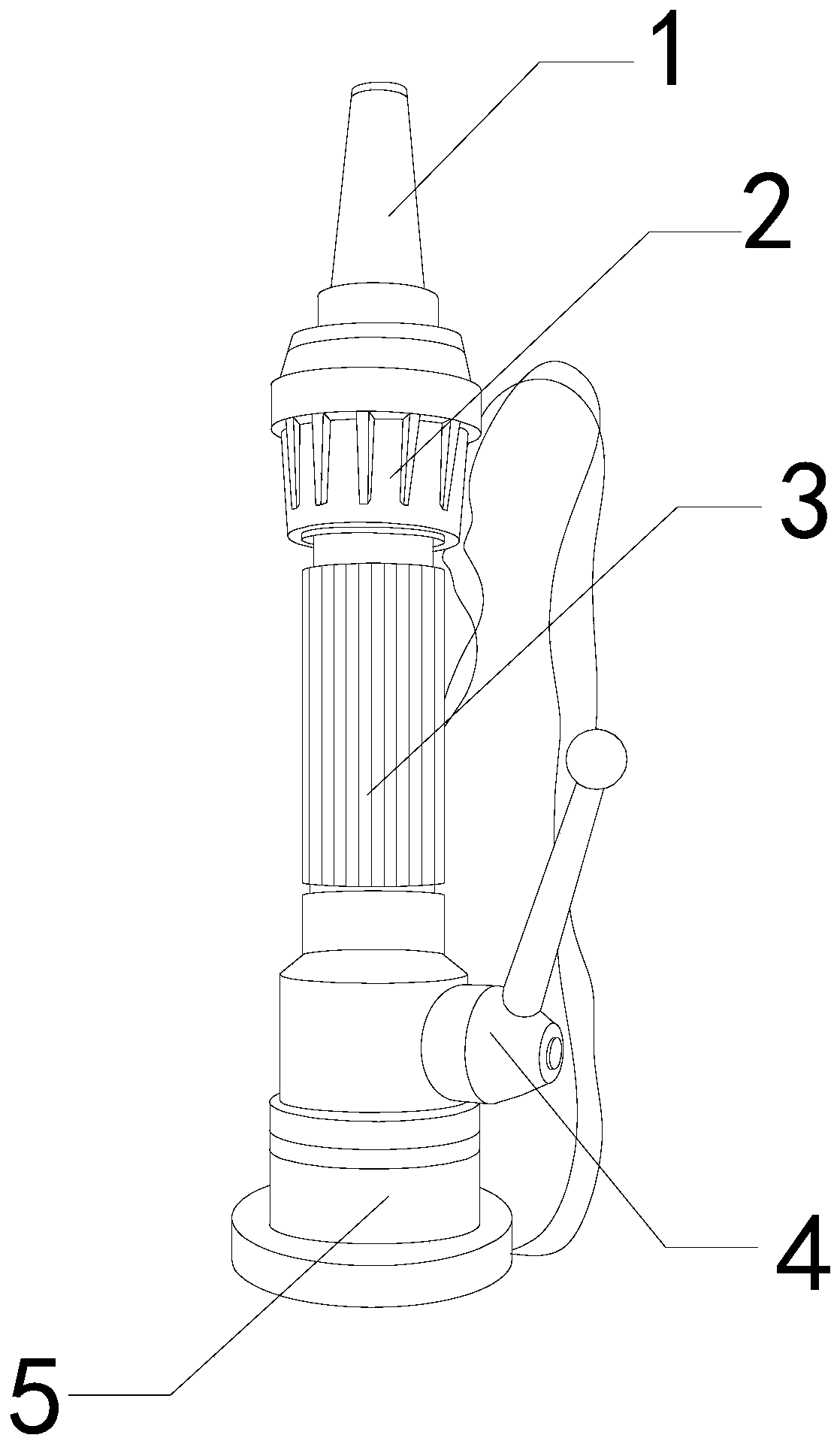
[0026] The invention provides a shock-absorbing fire-fighting water gun, the structure of which includes a spray head 1, a compression end 2, a conduit 3, a valve 4, and a connecting end 5. The conduit 3 is embedded in the lower end of the compression end 2, and the valve 4 It is movably engaged with the conduit 3 , the connecting end 5 is welded to the conduit 3 , and the spray head 1 is installed at the upper end of the compression end 2 .

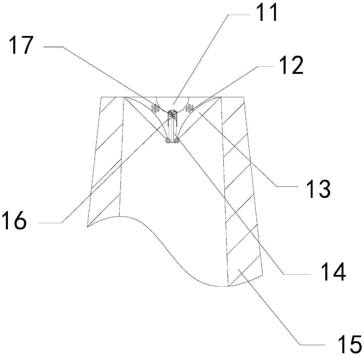
[0027] Wherein, the spray head 1 includes a resisting block 11, an elastic bar 12, a diffuser plate 13, a force bar 14, a frame body 15, a casing 16, and an elastic bar 17, and the resisting block 11 and the frame body 15 are an integrated structure. , the elastic bar 12 is installed between the resisting block 11 and the diffuser plate 13, the diffuser plate 13 is hingedly connected with the force bar 14, the force bar 14 is clearance-fitted with the casing 16, and the inside of ...

Embodiment 2

[0033] For example Figure 5 -example Figure 7 Shown:

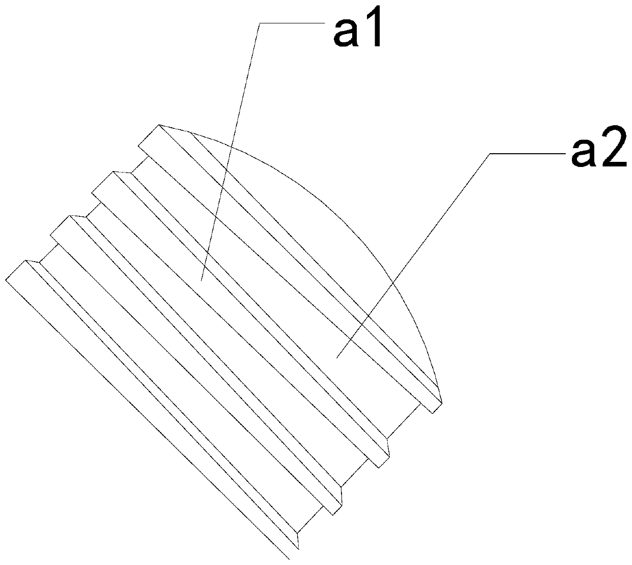
[0034] Wherein, the resisting block 11 includes a block body b1, a water guiding cavity b2, and a spraying mechanism b3. The water guiding cavity b2 and the block b1 are an integrated structure, and the spraying mechanism b3 is installed on the side of the water guiding cavity b2. At the upper end of the inner wall, the water guide chamber b2 is narrow at the top and wide at the bottom, which can enhance the water pressure of the water jet.

[0035] Wherein, the ejection mechanism b3 includes a top block b31, a water permeable hole b32, and a buffer mechanism b33. The water permeable hole b32 runs through the inner position of the top block b31, and the buffer mechanism b33 is installed at the bottom of the top block b31. The permeable hole b32 can disperse the water jetted from b13, avoiding the direct jetting flow of the water is too large, so that the quality is too large, resulting in the water falling too fast and...


PUM


Abstract

The invention discloses an anti-shock fire-fighting lance. The anti-shock fire-fighting lance structurally comprises a spraying head, a compression end, a guide pipe, a valve and a connection end, theguide pipe is fixed to the lower end of the compression end in an embedded mode, the valve is in movably clamping fit with the guide pipe, the connection end is welded to the guide pipe, and the spraying pipe is mounted at the upper end of the compression end. When fire-fighting water is sprayed from the interior of the spraying head, through thrust force of a sprayed water flow on a diffusion plate, the diffusion plate can be closed towards the middle in a swung mode along a force-bearing strip, thus the water flow can be sprayed out from a gas generated between the diffusion plate and the inner wall of a frame body, and thus the water flow can be sprayed out in a diffused shape; and the water guided-in by the force-bearing strip can be sprayed out through a water guiding cavity in a resisting block, the sprayed-out water can be dispersed through water-permeating holes in a spray-out mechanism, thus the covering area of the water flow sprayed out from the water guiding cavity can beincreased, and the fire-fighting efficiency is effectively improved.

Description

technical field [0001] The invention relates to the field of fire fighting, in particular to a shock-absorbing fire-fighting water gun. Background technique [0002] Shock-absorbing fire water nozzles are mainly used to quickly extinguish emergency fires. They can spray fire-fighting water at high pressure through the muzzle, so that the sprayed water can extinguish the aimed flames. It is a common equipment in public buildings. Based on From the above description, the inventors found that the existing shock-absorbing fire hose mainly has the following deficiencies, for example: [0003] Because the high-pressure sprayed water flow of the fire water gun is often in the shape of a straight water column, and the water pressure is high, so that it is too laborious to turn and spray. If the flame distribution area is large, the water column will not be able to quickly extinguish the large-area flame. lead to greater property damage. Contents of the invention [0004] In view...

Claims


Application Information

Patent Timeline
IPC IPC(8): A62C31/03A62C31/28
CPCA62C31/03A62C31/28
Inventor 黄建中
Owner 辽宁众成消防工程有限公司
Features
  • Generate Ideas
  • Intellectual Property
  • Life Sciences
  • Materials
  • Tech Scout
  • Unparalleled Data Quality
  • Higher Quality Content
  • 60% Fewer Hallucinations
Learn More