[0025] The technical solutions in the embodiments of the present invention will be clearly and completely described below in conjunction with the accompanying drawings in the embodiments of the present invention. Obviously, the described embodiments are only a part of the embodiments of the present invention, rather than all the embodiments. Based on the embodiments of the present invention, all other embodiments obtained by those of ordinary skill in the art without creative work shall fall within the protection scope of the present invention.
[0026] It should be noted that all the directional indications (such as up, down, left, right, front, back...) in the embodiments of the present invention are only used to explain the difference between components in a specific posture (as shown in the accompanying drawings). If the relative positional relationship, movement situation, etc. change, the directional indication will change accordingly.
[0027] In addition, the descriptions related to "first", "second", etc. in the present invention are only for descriptive purposes, and cannot be understood as indicating or implying their relative importance or implicitly indicating the number of indicated technical features. Therefore, the features defined with "first" and "second" may explicitly or implicitly include at least one of the features. In addition, the technical solutions between the various embodiments can be combined with each other, but they must be based on what can be achieved by those of ordinary skill in the art. When the combination of technical solutions is contradictory or cannot be achieved, it should be considered that such a combination of technical solutions does not exist. , Is not within the protection scope of the present invention.
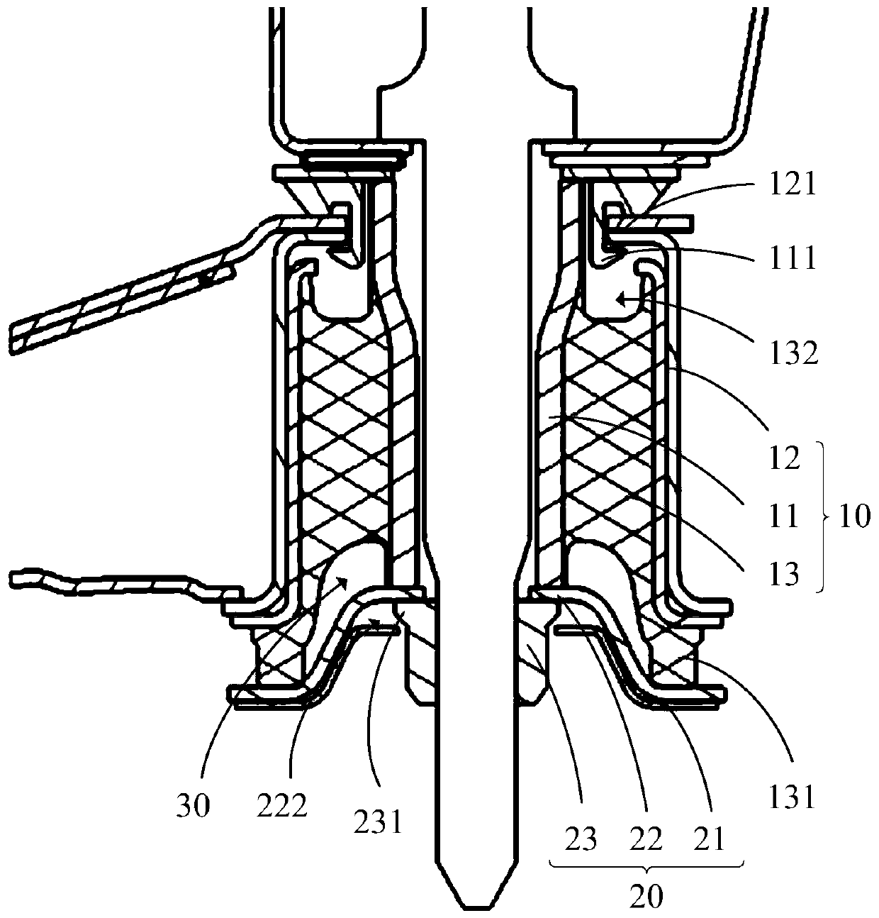
[0028] The present invention proposes a sub-frame buffer device, please refer to Figure 1 to Figure 4 , The sub-frame cushioning device includes a cushion 10 and a bowl cushion 20, the cushion 10 is disposed on the bowl cushion 20, and both the cushion 10 and the bowl cushion 20 are provided with a mating pair The through hole of the frame; wherein the liner 10 includes an inner sleeve 11, an outer sleeve 12, and a cushioning member 13, the outer sleeve 12 is wrapped around the inner sleeve 11, and the cushioning member 13 is disposed in the inner Between the sleeve 11 and the outer jacket 12; the bowl pad 20 includes a boss 22 and a support portion 21, the support portion 21 is arranged along the edge of the boss 22, the buffer 13 has an extension 131, The extension portion 131 extends from between the inner sleeve 11 and the outer sleeve 12 to between the outer sleeve 12 and the supporting portion 21, and abuts against the outer sleeve 12 and the supporting portion 21.
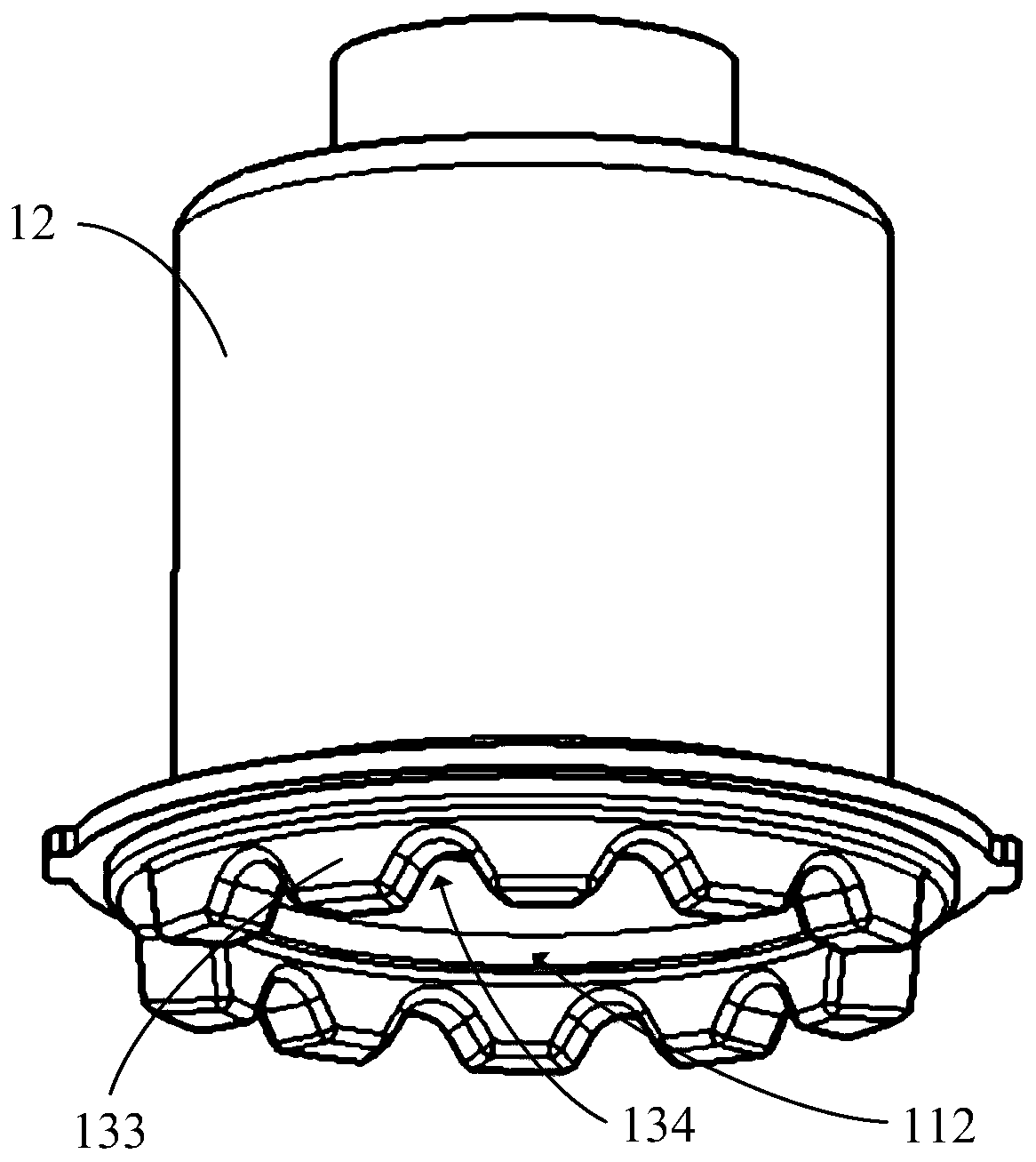
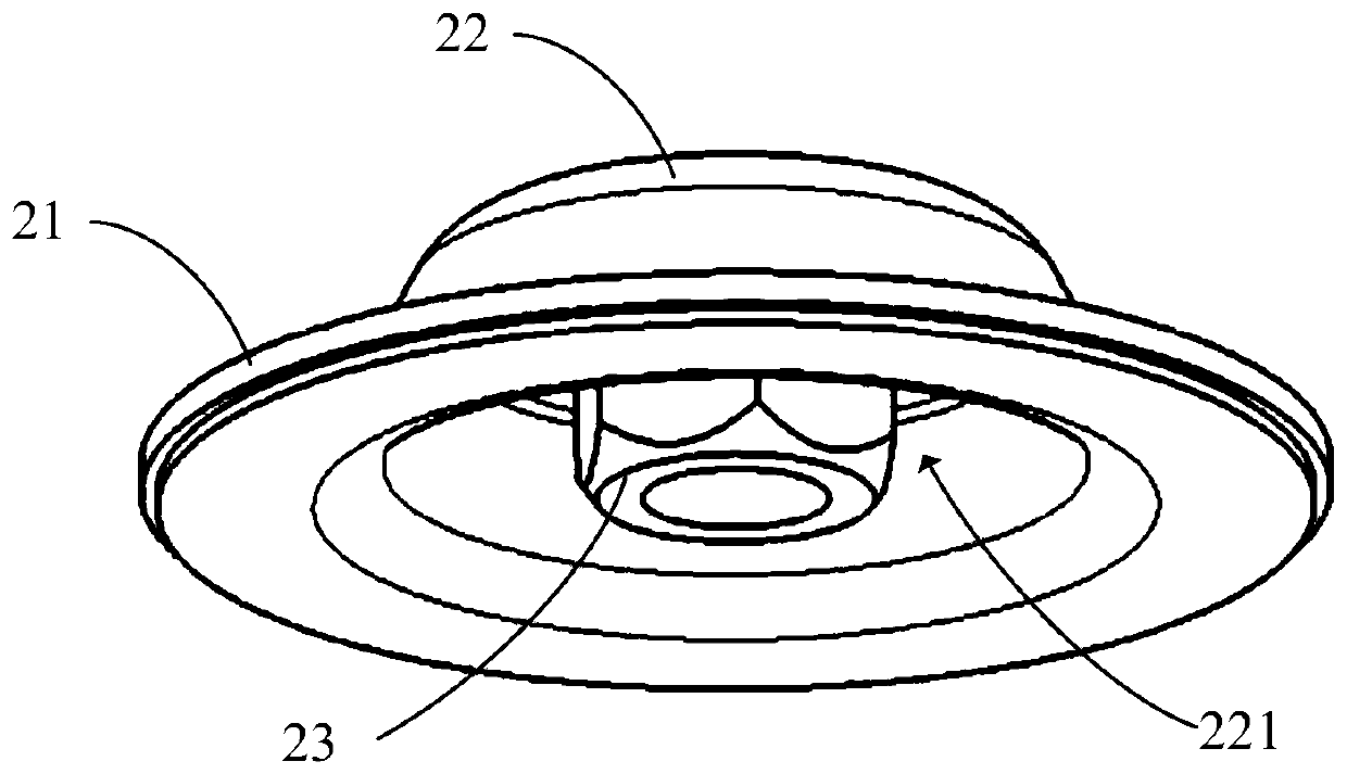
[0029] The pad 10 and the bowl pad 20 are inserted into the through hole through a sub-frame to achieve assembly. For details, please refer to Figure 1 to Figure 4 , The inner sleeve 11 is provided with a first through hole 112, the boss 22 is provided with a second through hole 221, the first through hole 112 and the second through hole 221 are arranged correspondingly, so as to realize the The sub-frame passes through the first through hole 112 and the second through hole 221 to assemble the pad 10 and the bowl pad 20.
[0030] The boss 22 has a bowl shape, one end of the boss 22 is set toward the cushion 10, and the edge of the boss 22 has a flanging that extends outward to form the support portion 21 . In this embodiment, in order to optimize the structure, the supporting portion 21 and the edge of the boss 22 are smoothly transitioned to ensure that the cushioning member 13 can be fully attached to the supporting portion 21, thereby improving the The cushioning capacity of the cushion 13.
[0031] The boss 22 protrudes toward the liner 10 and abuts the inner sleeve 11, that is, when the liner 10 is assembled with the bowl cushion 20, the inner sleeve 11 of the liner 10 In contact with the convex surface of the boss 22, the outer sleeve 12 is disposed opposite to the support portion 21. When the buffer 13 extends toward the support portion 21, the extension portion 131 extends from the inner The sleeve 11 and the outer sleeve 12 extend between the outer sleeve 12 and the supporting portion 21 and abut the outer sleeve 12 and the supporting portion 21. In this embodiment, in order to optimize the structure, the liner 10 is configured to be cylindrical, so that the liner 10 can completely fit the bowl cushion 20, that is, the inner sleeve 11 can be completely attached to the The boss 22 is on. It should be noted that this embodiment includes but is not limited to the above solutions. The size and shape of the pad 10 and the bowl pad 20 can be adjusted according to the frame size to improve the compatibility of the sub-frame cushioning device .
[0032] In addition, a buffer cavity 30 is formed between the buffer member 13, the inner sleeve 11 and the boss 22. In actual application, when the buffer member 13 is squeezed under the action of impact force, its extension 131 is squeezed between the inner sleeve 11 and the outer sleeve 12, which may cause the inner sleeve 11 or the outer jacket 12 is broken and damaged. Therefore, in this embodiment, a buffer cavity 30 is provided on the buffer 13 to provide a certain deformation space for the buffer 13 to avoid the The inner sleeve 11 or the outer sleeve 12 is damaged due to the impact force, which further improves the stability and reliability of the sub-frame buffer device of the present invention.
[0033] Specifically, the cushioning member 13 may be made of materials with cushioning properties such as rubber or plastic. When the sub-frame cushioning device is impacted, the extension 131 of the cushioning member 13 abuts against On the support portion 21, under the action of the impact force, the extension portion 131 is squeezed to produce deformation, thereby playing the role of vibration isolation and attenuation of the impact force, and since the deformation amount of the extension portion 131 after being squeezed is limited, Therefore, by controlling the deformation amount of the sub-frame buffer device, the stroke when it is under force can be limited, thereby further improving the buffering performance, and improving the comfort, smoothness and handling performance of the vehicle. In this embodiment, in order to further improve the stability of the cushioning member 13, the cushioning member 13 is in interference fit with the inner sleeve 11 and the outer sleeve 12, so as to prevent the cushioning member 13 from being affected by the impact force. The outer sleeve 12 and the inner sleeve 11 fall off.
[0034] In the technical solution of the present invention, an extension 131 is provided on the cushioning member 13. When the pad 10 is assembled with the bowl pad 20, the boss 22 abuts the inner sleeve 11, and the extension The portion 131 is in contact with the supporting portion 21, and the impact force is weakened by the deformation of the buffer member 13, so as to limit the stroke of the pad 10 and the bowl pad 20 when the force is applied, so as to a certain extent Improve the ride comfort, ride comfort and stability of the vehicle.
[0035] Further, the extension portion 131 is provided with a plurality of buffer teeth 133 toward the end that abuts the support portion 21, and the plurality of buffer teeth 133 are evenly distributed along the circumferential direction of the support portion 21 to ensure the extension The portion 131 is uniformly stressed in all directions to improve the cushioning performance of the sub-frame cushioning device. At the same time, there is an arc-shaped buffer groove 134 between two adjacent buffer teeth 133, and the slot of the arc-shaped buffer groove 134 faces the support portion 21. In this embodiment, when the buffer device of the sub-frame is impacted, the arc-shaped buffer groove 134 is provided between the buffer teeth 133, and therefore there is between the two adjacent buffer teeth 133. With more deformation space, it is possible to further improve the control of the deformation amount of the sub-frame buffer device and limit its stroke when subjected to force.
[0036] Specifically, a fixing member 23 is provided on the side of the boss 22 away from the liner 10 to fasten to the sub-frame, the boss 22 is provided with a limiting groove 222, and the fixing member 23 is A bump 231 is provided, and the bump 231 is clamped in the limiting groove 222 (the thing below 22). When the sub-frame is inserted into the first through hole 112 and the second through hole 221, it passes through the second through hole 221 and is connected to the fixing member 23, thereby connecting the gasket 10 Clamp with the bowl pad 20. In this embodiment, the fastener can be fastened to the sub-frame by using a nut. However, this embodiment includes but is not limited to the above solution, and the fastener can also be fastened and connected by means of bolts.
[0037] In the above process, when the impact force is received, in order to prevent the fixing member 23 from deviating and causing the fixing member 23 to fall off from the boss 22, the limiting groove 222 and the protrusion 231 are provided. The way of cooperation is to limit the position of the fixing member 23, thereby further improving the stability and reliability of the sub-frame buffer device of the present invention.
[0038] Specifically, please refer to figure 1 , The outer sleeve 12 is provided with a clamping plate 121, the inner sleeve 11 is provided with a buckle 111, the buffer member 13 is provided with an escape groove 132, and the buckle 111 extends into the escape groove 132 and It is clamped on the card board 121.
[0039] As an embodiment, in this embodiment, in order to simplify the structure, the clamping plate 121 is arranged at the end of the outer sleeve 12 facing away from the bowl pad 20, and the clamping plate 121 extends toward the inner sleeve 11. And an opening is formed between the side wall of the inner sleeve 11, the buckle 111 is disposed on the top of the inner sleeve 11, and the buckle 111 extends toward the card plate 121 and extends from the opening position. To be buckled on the card plate 121, and the escape groove 132 is provided at a position corresponding to the opening of the buffer member 13, so as to ensure that the buckle 111 can extend from the opening to realize the inner sleeve 11 The connection with the jacket 12.
[0040] Wherein, the positions of the buckle 121 and the buckle 111 can be replaced with each other, that is, the buckle 121 can be arranged on the inner sleeve 11, and the buckle 111 can be arranged on the outer sleeve. 12 to realize the connection between the inner sleeve 11 and the outer sleeve 12.
[0041] It should be noted that the present invention includes but is not limited to the above solutions. In order to further improve the compatibility of the sub-frame buffer device, the card board 121 can be arranged at any position of the outer casing 12, and only the The buckle 111 may be provided on the inner sleeve 11 at a position corresponding to the buckle 121. In this way, the positions of the buckle 111 and the buckle 121 can be adjusted according to application scenarios to meet different requirements.
[0042] In addition, in order to solve the above problems, the present invention also provides a sub-frame, please refer to Figure 5 The sub-frame includes a vehicle body and the above-mentioned sub-frame buffer device, and the sub-frame buffer device is arranged on the vehicle body.
[0043] The pad 10 and the bowl pad 20 are inserted into the through hole through a sub-frame to achieve assembly. For details, please refer to Figure 1 to Figure 4 , The inner sleeve 11 is provided with a first through hole 112, the boss 22 is provided with a second through hole 221, the first through hole 112 and the second through hole 221 are arranged correspondingly, so as to realize the The sub-frame passes through the first through hole 112 and the second through hole 221 to assemble the pad 10 and the bowl pad 20.
[0044] The boss 22 has a bowl shape, one end of the boss 22 is set toward the cushion 10, and the edge of the boss 22 has a flanging that extends outward to form the support portion 21 . In this embodiment, in order to optimize the structure, the supporting portion 21 and the edge of the boss 22 are smoothly transitioned to ensure that the cushioning member 13 can be fully attached to the supporting portion 21, thereby improving the The cushioning capacity of the cushion 13.
[0045] The boss 22 protrudes toward the liner 10 and abuts the inner sleeve 11, that is, when the liner 10 is assembled with the bowl cushion 20, the inner sleeve 11 of the liner 10 In contact with the convex surface of the boss 22, the outer sleeve 12 is disposed opposite to the support portion 21. When the buffer 13 extends toward the support portion 21, the extension portion 131 extends from the inner The sleeve 11 and the outer sleeve 12 extend between the outer sleeve 12 and the supporting portion 21 and abut the outer sleeve 12 and the supporting portion 21. In this embodiment, in order to optimize the structure, the liner 10 is configured to be cylindrical, so that the liner 10 can completely fit the bowl cushion 20, that is, the inner sleeve 11 can be completely attached to the The boss 22 is on. It should be noted that this embodiment includes but is not limited to the above solutions. The size and shape of the pad 10 and the bowl pad 20 can be adjusted according to the frame size to improve the compatibility of the sub-frame cushioning device .
[0046] In addition, a buffer cavity 30 is formed between the buffer member 13, the inner sleeve 11 and the boss 22. In actual application, when the buffer member 13 is squeezed under the action of impact force, its extension 131 is squeezed between the inner sleeve 11 and the outer sleeve 12, which may cause the inner sleeve 11 or the outer jacket 12 is broken and damaged. Therefore, in this embodiment, a buffer cavity 30 is provided on the buffer 13 to provide a certain deformation space for the buffer 13 to avoid the The inner sleeve 11 or the outer sleeve 12 is damaged due to the impact force, which further improves the stability and reliability of the sub-frame buffer device of the present invention.
[0047] Specifically, the cushioning member 13 may be made of materials with cushioning properties such as rubber or plastic. When the sub-frame cushioning device is impacted, the extension 131 of the cushioning member 13 abuts against On the support portion 21, under the action of the impact force, the extension portion 131 is squeezed to produce deformation, thereby playing the role of vibration isolation and attenuation of the impact force, and since the deformation amount of the extension portion 131 after being squeezed is limited, Therefore, by controlling the deformation amount of the sub-frame buffer device, the stroke when it is under force can be limited, thereby further improving the buffering performance, and improving the comfort, smoothness and handling performance of the vehicle. In this embodiment, in order to further improve the stability of the cushioning member 13, the cushioning member 13 is in interference fit with the inner sleeve 11 and the outer sleeve 12, so as to prevent the cushioning member 13 from being affected by the impact force. The outer sleeve 12 and the inner sleeve 11 fall off.
[0048] In the technical solution of the present invention, an extension 131 is provided on the cushioning member 13. When the pad 10 is assembled with the bowl pad 20, the boss 22 abuts the inner sleeve 11, and the extension The portion 131 is in contact with the supporting portion 21, and the impact force is weakened by the deformation of the buffer member 13, so as to limit the stroke of the pad 10 and the bowl pad 20 when the force is applied, so as to a certain extent Improve the ride comfort, ride comfort and stability of the vehicle.
[0049] In addition, in order to solve the above-mentioned problems, the present invention also proposes an automobile. The automobile includes an automobile body and a subframe as described above, and the subframe is arranged on the automobile body.
[0050] The pad 10 and the bowl pad 20 are inserted into the through hole through a sub-frame to achieve assembly. For details, please refer to Figure 1 to Figure 4 , The inner sleeve 11 is provided with a first through hole 112, the boss 22 is provided with a second through hole 221, the first through hole 112 and the second through hole 221 are arranged correspondingly, so as to realize the The sub-frame passes through the first through hole 112 and the second through hole 221 to assemble the pad 10 and the bowl pad 20.
[0051] The boss 22 has a bowl shape, one end of the boss 22 is set toward the cushion 10, and the edge of the boss 22 has a flanging that extends outward to form the support portion 21 . In this embodiment, in order to optimize the structure, the supporting portion 21 and the edge of the boss 22 are smoothly transitioned to ensure that the cushioning member 13 can be fully attached to the supporting portion 21, thereby improving the The cushioning capacity of the cushion 13.
[0052] The boss 22 protrudes toward the liner 10 and abuts the inner sleeve 11, that is, when the liner 10 is assembled with the bowl cushion 20, the inner sleeve 11 of the liner 10 In contact with the convex surface of the boss 22, the outer sleeve 12 is disposed opposite to the support portion 21. When the buffer 13 extends toward the support portion 21, the extension portion 131 extends from the inner The sleeve 11 and the outer sleeve 12 extend between the outer sleeve 12 and the supporting portion 21 and abut the outer sleeve 12 and the supporting portion 21. In this embodiment, in order to optimize the structure, the liner 10 is configured to be cylindrical, so that the liner 10 can completely fit the bowl cushion 20, that is, the inner sleeve 11 can be completely attached to the The boss 22 is on. It should be noted that this embodiment includes but is not limited to the above solutions. The size and shape of the pad 10 and the bowl pad 20 can be adjusted according to the frame size to improve the compatibility of the sub-frame cushioning device .
[0053] In addition, a buffer cavity 30 is formed between the buffer member 13, the inner sleeve 11 and the boss 22. In actual application, when the buffer member 13 is squeezed under the action of impact force, its extension 131 is squeezed between the inner sleeve 11 and the outer sleeve 12, which may cause the inner sleeve 11 or the outer jacket 12 is broken and damaged. Therefore, in this embodiment, a buffer cavity 30 is provided on the buffer 13 to provide a certain deformation space for the buffer 13 to avoid the The inner sleeve 11 or the outer sleeve 12 is damaged due to the impact force, which further improves the stability and reliability of the sub-frame buffer device of the present invention.
[0054] Specifically, the cushioning member 13 may be made of materials with cushioning properties such as rubber or plastic. When the sub-frame cushioning device is impacted, the extension 131 of the cushioning member 13 abuts against On the support portion 21, under the action of the impact force, the extension portion 131 is squeezed to produce deformation, thereby playing the role of vibration isolation and attenuation of the impact force, and since the deformation amount of the extension portion 131 after being squeezed is limited, Therefore, by controlling the deformation amount of the sub-frame buffer device, the stroke when it is under force can be limited, thereby further improving the buffering performance, and improving the comfort, smoothness and handling performance of the vehicle. In this embodiment, in order to further improve the stability of the cushioning member 13, the cushioning member 13 is in interference fit with the inner sleeve 11 and the outer sleeve 12, so as to prevent the cushioning member 13 from being affected by the impact force. The outer sleeve 12 and the inner sleeve 11 fall off.
[0055] In the technical solution of the present invention, an extension 131 is provided on the cushioning member 13. When the pad 10 is assembled with the bowl pad 20, the boss 22 abuts the inner sleeve 11, and the extension The portion 131 is in contact with the supporting portion 21, and the impact force is weakened by the deformation of the buffer member 13, so as to limit the stroke of the pad 10 and the bowl pad 20 when the force is applied, so as to a certain extent Improve the ride comfort, ride comfort and stability of the vehicle.
[0056] The above descriptions are only the preferred embodiments of the present invention and do not limit the scope of the present invention. Any equivalent structural transformations or direct/indirect applications made by using the contents of the description and drawings of the present invention under the inventive concept of the present invention Other related technical fields are included in the scope of patent protection of the present invention.