Device and method for judging AMT vehicle clutch half-bonding point

A technology of semi-engagement and clutch position, applied in transmission control, elements with teeth, belts/chains/gears, etc., can solve the problem that AMT vehicles are not smooth enough during gear shifting, and the semi-engagement of clutch is not accurate enough. Reliability, affecting AMT vehicle control and other issues, to achieve the effect of reducing fluctuation, reducing friction, and improving accuracy

Inactive Publication Date: 2008-06-04
BYD CO LTD
0 Cites 17 Cited by

AI-Extracted Technical Summary

Problems solved by technology

At present, due to factors such as clutch friction, the collected half-engagement point of the clutch is not accurate and reliab...

Abstract

The invention discloses a device and a method for judging AMT vehicle clutch half joint. The device comprises a signal collecting unit and an electronic control unit, wherein the signal collecting unit comprises an engine speed sensor, a speed change gear shaft speed sensor and a clutch position sensor which are respectively connected with an electronic control unit. The control unit is used for collecting a clutch position signal sent by the clutch position sensor when the engine speed is less than a first preset value after an AMT vehicle enters P shift and the absolute value of the speed change gear shaft speed difference is less than a second preset value. The invention can improve the accuracy of collected clutch half joint, thereby improving the running smoothness of the vehicle, reducing clutch wear, prolonging clutch service life, ensuring steady running of the engine and reducing engine speed fluctuation.

Application Domain

Technology Topic

Image

  • Device and method for judging AMT vehicle clutch half-bonding point
  • Device and method for judging AMT vehicle clutch half-bonding point
  • Device and method for judging AMT vehicle clutch half-bonding point

Examples

  • Experimental program(1)

Example Embodiment

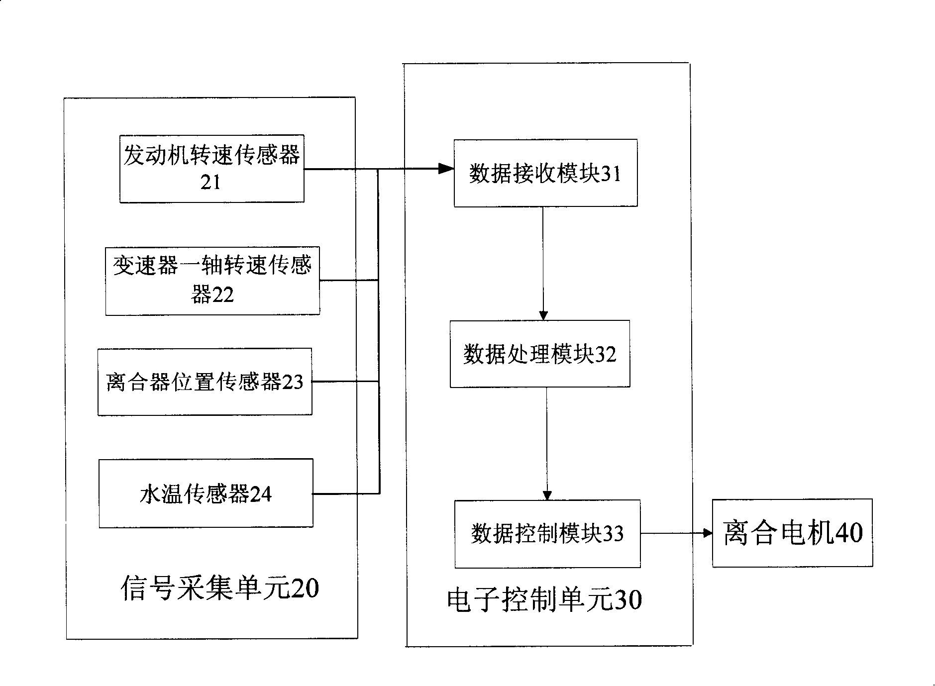
[0027] Such as figure 1 As shown, a device for judging a clutch half joint for an AMT vehicle includes a signal acquisition unit 20 and an electronic control unit 30; the electronic control unit 30 includes a data receiving module 31, a data processing module 32, and a data control module 33; The data receiving module 31 is electrically connected to the signal acquisition unit 20, and the data control module 33 is electrically connected to the clutch motor 40. The signal acquisition unit 20 includes an engine speed sensor 21, a transmission one shaft speed sensor 22, and a clutch position sensor 23; the data receiving module 31 is used to receive the engine speed signal collected by the engine speed sensor 21 of the signal acquisition unit, and the transmission one shaft The rotational speed signal of the first shaft of the transmission collected by the rotational speed sensor 22, and the clutch position signal collected by the clutch position sensor 23. The data processing module 32 is used for when the AMT vehicle enters the P gear, the engine speed is less than the first predetermined value and the rotational speed of the engine and the transmission shaft When the absolute value of the difference is less than the second predetermined value, the clutch position signal of the clutch position sensor 23 is collected, and the collected clutch position signal corresponds to the clutch half-engagement point of the AMT vehicle. The first predetermined value is preferably 1000 revolutions per minute, and the second predetermined value is preferably 20 revolutions per minute. Among them, the transmission shaft refers to the input shaft of the transmission, which is used to transmit the torque from the engine.
[0028] Wherein, the engine speed sensor 21 is preferably a magnetoelectric speed sensor or a photoelectric speed sensor, which is located on the engine and is used to detect the speed of the engine. The speed sensor 22 of the first shaft of the transmission is preferably a magnetoelectric speed sensor or a photoelectric speed sensor, which is located near the first shaft of the transmission and is used to detect the speed of the first shaft of the transmission. The clutch position sensor 23 is preferably a potentiometer type angular displacement sensor, which is located on the clutch and is used to detect the opening and closing state of the clutch.
[0029] The data receiving module 31 includes a voltage stabilizing circuit and/or an A/D conversion circuit, which is used to stabilize the analog signal input by the signal acquisition unit 20 and/or convert it into a digital signal for the data processing module 32 to perform analysis and processing.
[0030] The data control module 33 may include an amplifying circuit and/or a D/A conversion circuit for amplifying and/or converting the clutch control signal into an analog signal to drive the clutch motor 40 controlled by the electronic control unit 30. The clutch motor 40 is connected to the clutch when it is installed. The clutch motor 40 also includes a clutch motor drive circuit. The clutch motor drive circuit can adopt a dedicated integrated drive chip for the motor or a bridge circuit composed of discrete components for driving the clutch motor 40 to move forward and backward.
[0031] Preferably, the data processing module 32 may further include a filtering module for filtering the collected clutch position signals.
[0032] Preferably, the data receiving module 31, the data processing module 32, and the data control module 33 are integrated on one or more integrated circuit boards with single-chip microcomputers.
[0033] Preferably, the signal collection unit 20 may further include a water temperature sensor 24, which is located in the cooling water pipe of the engine, and is used to detect the water temperature of the cooling water of the engine. The output terminal of the water temperature sensor 24 and the data receiving module 31 The input terminal is connected. The data processing module 32 is also used for receiving the water temperature signal output by the data receiving module 31, and correcting the clutch position signal of the clutch position sensor 23 according to the water temperature signal.
[0034] Such as figure 2 As shown, a method for an AMT vehicle to determine a clutch half-engagement point includes the following steps:
[0035] The first step: the AMT vehicle enters the park (Park, referred to as P) gear and then enters the second step.
[0036] The second step: the data processing module 32 judges whether the engine speed output by the data receiving module 31 is less than the first predetermined value, if it is, enter the third step, if not, wait.
[0037] The third step: the data processing module 32 judges whether the absolute value of the difference between the engine speed output by the data receiving module 31 and the transmission shaft speed is less than the second predetermined value, if yes, proceed to the fourth step, if otherwise, wait.
[0038] Step 4: The data processing module 32 records the clutch position signal output by the data receiving module 31. The clutch position signal corresponds to the clutch half-engagement point of the AMT vehicle.
[0039] Preferably, in the fourth step, the data processing module 32 also performs filtering processing on the clutch position signal.
[0040] Preferably, in the fourth step, the data processing module 32 also corrects the clutch position signal output by the clutch position sensor 23 according to the water temperature signal output by the water temperature sensor 24. The correction method is as follows: when the water temperature signal is lower than the standard value, the data processing module 32 is used to subtract a coefficient from the clutch position signal of the clutch position sensor 23; when the water temperature signal is higher than the standard value, the data processing module 32 is used to correct The clutch position signal of the clutch position sensor 23 adds a coefficient.
[0041] Combine below image 3 Briefly explain the process of clutch coupling: the coupling of the clutch should be divided into four stages: the idle stroke stage, the overcoming resistance stage, the acceleration stage, and the non-slip phase.
[0042]The idle stroke stage is used to eliminate the gap between the clutch plates, and there is no torque transmission. correspond image 3 In the AB section, in consideration of reducing the time for shifting power interruption, this stage should be combined quickly. In the phase of overcoming the resistance, slip friction is generated between the clutch's main and driven plates, but the torque transmitted by the clutch cannot overcome the maximum rolling resistance moment of the automobile, and the vehicle continues to travel by inertia. At this stage, the condition of the whole vehicle is not affected, but slip friction of the clutch can be generated, corresponding to image 3 In the BC section, this stage should be combined quickly to reduce sliding work. During the acceleration phase, the torque transmitted between the clutch's main and follower plates exceeds the maximum rolling resistance torque. Changes in the torque transmitted by the clutch will cause shocks, so this stage should be combined slowly to obtain a smooth shift, improve the ride comfort of the occupants and reduce the impact load of the driveline. At the same time, the coupling time should not be too long, otherwise the slipping time will be too long, which will cause the clutch to overheat and affect its life. This stage corresponds to image 3 In the CD segment. In the non-slip phase, the clutch master-slave and the rotor plate begin to synchronize. The acceleration and impact of the car depend on the output torque of the engine, and there is no slip-friction work. At this time, the combination of the clutch has no effect on the shift quality, so Considering that the gear shift should be completed as soon as possible, this stage should be combined quickly, and this stage corresponds to image 3 In the DE segment. Point B in the figure corresponds to the half-engagement point of the clutch of the AMT vehicle.
[0043] From the above analysis, it can be seen that the coupling process of the entire shift clutch is a "fast-slow-fast" coupling process. image 3 The middle Tf is the resistance torque converted to the input shaft of the transmission. TC is the transmission torque of the clutch.
[0044] Through the above analysis, it can be known that the device for judging the clutch half joint point of the present invention for AMT vehicles has a reasonable structure and good performance. The test results also show the correctness and rationality of judging the clutch control system. Thereby improving the smoothness of shifting and the control performance of the vehicle. It also provides a more practical method for the transformation of the AMT electronic control system.

PUM

no PUM

Description & Claims & Application Information

We can also present the details of the Description, Claims and Application information to help users get a comprehensive understanding of the technical details of the patent, such as background art, summary of invention, brief description of drawings, description of embodiments, and other original content. On the other hand, users can also determine the specific scope of protection of the technology through the list of claims; as well as understand the changes in the life cycle of the technology with the presentation of the patent timeline. Login to view more.

Similar technology patents

Method and device for forecasting reservoir yield

InactiveCN101906966AHigh precisionSurveyWellheadVolume factor
Owner:PETROCHINA CO LTD

Classification and recommendation of technical efficacy words

  • Improve ride comfort
  • High precision

Vibration reducer assembly and buffer block structure thereof

ActiveCN104864016AImprove ride comfortImproved ability to resist shock loadsElastic dampersShock absorbersBlock structureEngineering
Owner:GUANGZHOU AUTOMOBILE GROUP CO LTD
Why Eureka
Try Eureka