A gas diversion control device for a combustion chamber

A diversion control, combustion chamber technology, applied in combustion chambers, continuous combustion chambers, combustion methods, etc., can solve the problems of polluted gas, waste of resources, high flame front temperature, etc., achieve low combustion emissions and ensure air supply pressure , the effect of uniform temperature distribution

Active Publication Date: 2022-01-11
萧县煜成石油设备有限公司
View PDF5 Cites 0 Cited by
  • Summary
  • Abstract
  • Description
  • Claims
  • Application Information

AI Technical Summary

Problems solved by technology

[0002] Combustors are commonly used in industrial production and power generation operations to ignite fuel to produce high temperature and high pressure combustion gases. Various competing considerations affect the design and operation of combustors. For example, higher combustion gas temperatures often result in Increases the thermodynamic efficiency of the combustor, however, higher combustion gas temperatures can also promote flashback or flame holding conditions in which the combustion flame moves toward the fuel supplied by the nozzle, potentially destroying the In addition, the combustion chamber should achieve low pollution emissions and reduce air pollution. At this time, an environmentally friendly and low-pollution combustion chamber gas diversion control device is needed
[0003] In the existing gas diversion control device of the combustion chamber, since the chemical reaction of the combustion mode of the combustion chamber is concentrated on a relatively narrow flame surface, the temperature distribution is uneven, and the temperature of the flame front is high, resulting in insufficient combustion. The generation of polluting gas is a waste of resources and pollutes the environment, which is not conducive to environmental protection. Therefore, we propose a gas diversion control device for the combustion chamber

Method used


Image

  • A gas diversion control device for a combustion chamber
  • A gas diversion control device for a combustion chamber
  • A gas diversion control device for a combustion chamber

Examples


Embodiment

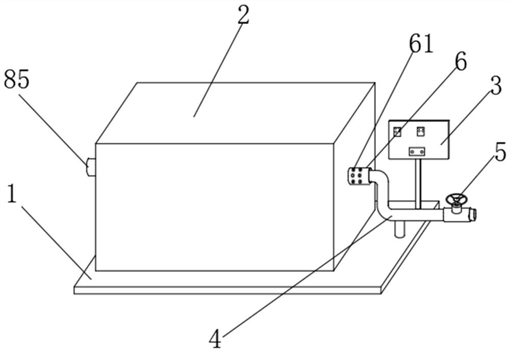
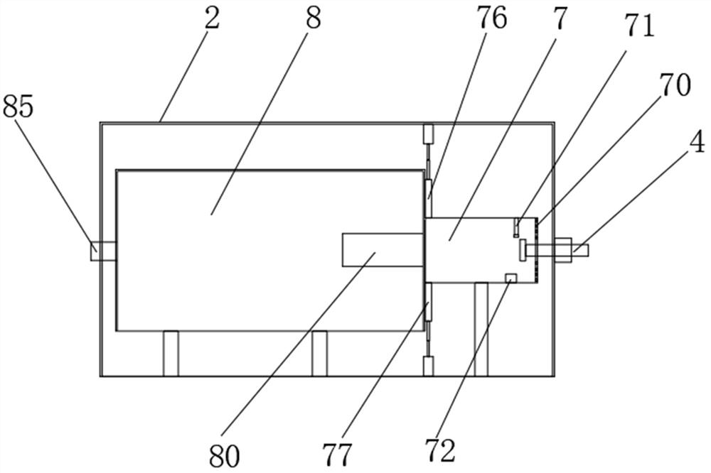
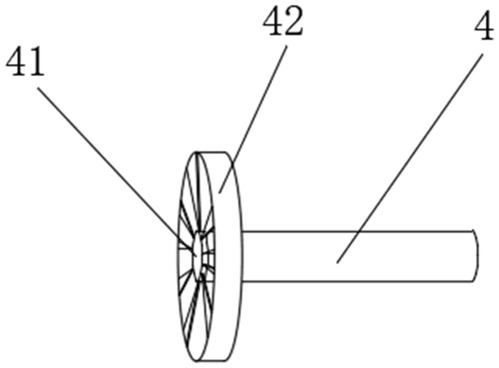
[0030] like Figure 1-7 As shown, a gas flow control device of a combustion chamber includes a base (1), the outer casing (2), and the control panel (3), the outer casing (2) is fixed to the upper end surface of the base (1), the control panel ( 3) Located in the upper end surface of the base (1), and the control panel (3) is located on one side of the outer casing (2), and a mount (6) is provided on one side of the outer casing (2), and the mounting tube (6) The inside is hollow, and the outer circumference of the mounting tube (6) is provided with auxiliary intake hole (61) such as a symmetric symmetric setting, and the base (1) is also provided with a gas pipe (4), gas pipe (4). One end is inserted inside the mounting cylinder (6), and the external air enters the interior of the outer casing (2) from the inside of the mounting tube (6), and the inside of the outer casing (2), one end of the gas pipe (4) runs through the installation The cartridge (6) and extends to the interior ...


PUM


Abstract

The invention discloses a gas diversion control device for a combustion chamber, which comprises a base, an outer shell and a control panel. A pre-combustion chamber and a main combustion chamber are arranged inside the outer shell, and the pre-combustion chamber is located at the side of the main combustion chamber. On one side, a pre-combustion outlet is provided on the end surface of the pre-combustion chamber away from the installation cylinder, and four sets of installation holes are provided on the end surface of the pre-combustion chamber near the pre-combustion outlet. A restrictor plate, a second restrictor plate, a third restrictor plate and a fourth restrictor plate. The gas diversion control device of the combustion chamber of the present invention can adjust the injection speed of the gas through the set first flow limiter, the second flow limiter, the third flow limiter and the fourth flow limiter, and through the set upper partition The plate and the lower partition can adjust the size of the combustion space of the main combustion chamber. By setting the heat storage partition, it can be used to store heat and increase the return flow of flue gas, so that the fuel can be fully burned, forming flameless and smokeless combustion, and burning pollutants. Low, more environmentally friendly, more practical.

Description

Technical field [0001] The present invention relates to an electric booster seat backrest walker technology, and particularly relates to one kind of combustion gas flow control means. Background technique [0002] The chamber is generally used for industrial production and power generation operations to ignite fuel to produce combustion gas of high temperature and pressure, the various competing considerations influence the design and operation of combustion chambers, for example, higher combustion gas temperatures generally improve the thermodynamic efficiency of the combustion chamber, however, higher combustion gas temperatures also trigger flashback or flame holding conditions, under these conditions, the combustion flame towards the fuel supplied by the nozzle moving, possibly in a relatively short period of time cause serious damage to the nozzle, further, low emission combustion chamber should do, reduce air pollution, the gas flow then need an environmentally pollution co...

Claims


Application Information

Patent Timeline
Patent Type & Authority Patents(China)
IPC IPC(8): F23R3/16F23R3/28F23R3/42
CPCF23R3/28F23R3/16F23R3/42
Inventor 便秋莞刘行刘太敏李庆峰
Owner 萧县煜成石油设备有限公司
Why Eureka
Try Eureka