Gas flow guiding device for combustion chamber

A technology of diversion control and combustion chamber, applied in the direction of combustion chamber, continuous combustion chamber, combustion method, etc., can solve the problems of waste of resources, high flame front temperature, unfavorable environmental protection, etc., to ensure air supply pressure, uniform temperature distribution, The effect of facilitating full combustion

Active Publication Date: 2020-08-28
萧县煜成石油设备有限公司
View PDF5 Cites 0 Cited by
  • Summary
  • Abstract
  • Description
  • Claims
  • Application Information

AI Technical Summary

Problems solved by technology

[0002] Combustors are commonly used in industrial production and power generation operations to ignite fuel to produce high temperature and high pressure combustion gases. Various competing considerations affect the design and operation of combustors. For example, higher combustion gas temperatures often result in Increases the thermodynamic efficiency of the combustor, however, higher combustion gas temperatures can also promote flashback or flame holding conditions in which the combustion flame moves toward the fuel supplied by the nozzle, potentially destroying the In addition, the combustion chamber should achieve low pollution emissions and reduce air pollution. At this time, an environmentally friendly and low-pollution combustion chamber gas diversion control device is needed
[0003] In the existing gas diversion control device of the combustion chamber, since the chemical reaction of the combustion mode of the combustion chamber is concentrated on a relatively narrow flame surface, the temperature distribution is uneven, and the temperature of the flame front is high, resulting in insufficient combustion. The generation of polluting gas is a waste of resources and pollutes the environment, which is not conducive to environmental protection. Therefore, we propose a gas diversion control device for the combustion chamber

Method used


Image

  • Gas flow guiding device for combustion chamber
  • Gas flow guiding device for combustion chamber
  • Gas flow guiding device for combustion chamber

Examples


Embodiment

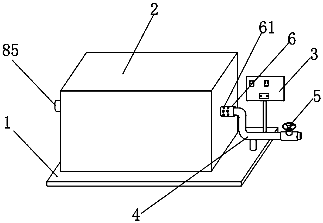
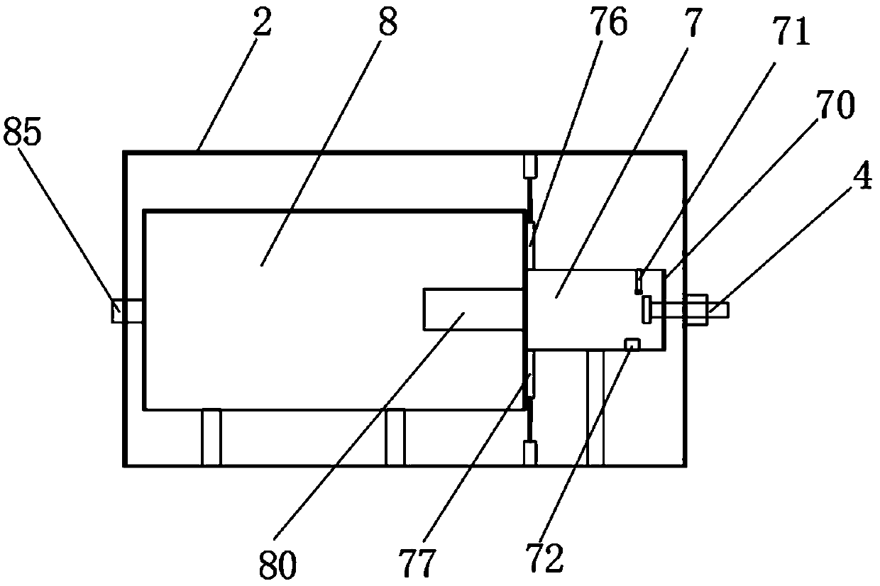
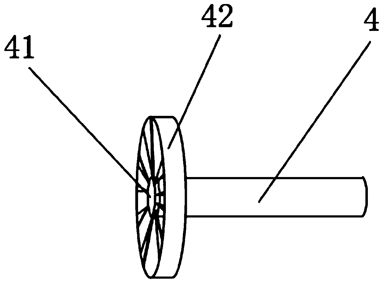
[0030] Such as Figure 1-7 As shown, a gas diversion control device for a combustion chamber includes a base (1), an outer shell (2) and a control panel (3), the outer shell (2) is fixed on the upper surface of the base (1), and the control panel ( 3) It is located on the upper end surface of the base (1), and the control panel (3) is located on one side of the outer shell (2), and one side of the outer shell (2) is provided with an installation cylinder (6), and the installation cylinder (6) The interior is hollow, and the outer circumference of the installation cylinder (6) is provided with auxiliary air intake holes (61) arranged symmetrically in groups, and a gas pipe (4) is also arranged above the base (1), and the gas pipe (4) One end is inserted inside the installation cylinder (6), the external air enters the interior of the outer casing (2) from the inside of the installation cylinder (6) and several groups of auxiliary air intake holes (61), and one end of the gas pi...


PUM


Abstract

The invention discloses a gas flow guiding device for a combustion chamber. The gas flow guiding device comprises a base, an outer shell and a control panel, wherein a pre-combustion chamber and a main combustion chamber are arranged inside the outer shell, the pre-combustion chamber is located on one side of the main combustion chamber, a pre-combustion outlet is formed in one end face, far awayfrom the pre-combustion chamber of a mounting cylinder, four sets of mounting holes are formed in the end face, close to the pre-combustion outlet pre-combustion chamber, and a first flow-limiting plate, a second flow-limiting plate, a third flow-limiting plate and a fourth flow-limiting plate are sequentially mounted in the four sets of mounting holes. According to the gas flow guiding device forthe combustion chamber, the injection speed of gas can be adjusted through the first flow-limiting plate, the second flow-limiting plate, the third flow-limiting plate and the fourth flow-limiting plate; by arranging an upper partition plate and a lower partition plate, the size of the combustion space of the main combustion chamber can be adjusted; and by arranging heat storage partition plates,heat can be stored, the flue gas reflux is increased, fuel can be sufficiently combusted, the flame-free smokeless combustion is formed, the combustion emission pollutant is low, and the gas flow guiding device is more environment-friendly and more practical.

Description

technical field [0001] The invention relates to the technical field of seat backrests of electric power-assisted walking aids, in particular to a gas diversion control device for a combustion chamber. Background technique [0002] Combustors are commonly used in industrial production and power generation operations to ignite fuel to produce high temperature and high pressure combustion gases. Various competing considerations affect the design and operation of combustors. For example, higher combustion gas temperatures often result in Increases the thermodynamic efficiency of the combustor, however, higher combustion gas temperatures can also promote flashback or flame holding conditions in which the combustion flame moves toward the fuel supplied by the nozzle, potentially destroying the The nozzle causes serious damage. In addition, the combustion chamber should achieve low pollution emissions and reduce air pollution. At this time, an environmentally friendly and low-pollu...

Claims


Application Information

Patent Timeline
IPC IPC(8): F23R3/16F23R3/28F23R3/42
CPCF23R3/28F23R3/16F23R3/42
Inventor 便秋莞刘行刘太敏李庆峰
Owner 萧县煜成石油设备有限公司
Why Eureka
Try Eureka