Handle grip with heater

a technology of hand grip and heater, which is applied in the direction of steering devices, cycle equipments, electric heating circuits, etc., can solve the problems of fpc plates that are difficult to handle, affecting the environment, and the temperature rise characteristic of a power supply is not sufficiently high, so as to achieve uniform temperature distribution, reduce the amount of materials, and reduce the effect of cos

Inactive Publication Date: 2007-01-11
HONDA ACCESS CORP +1
View PDF16 Cites 44 Cited by
  • Summary
  • Abstract
  • Description
  • Claims
  • Application Information

AI Technical Summary

Benefits of technology

[0013] In the handle grip with heater according to the invention, since the heater unit is formed as a surface type heat-generating member, a uniform temperature distribution can be obtained. Moreover, the handle grip with heater according to the invention can be manufactured in an easy and less expensive manner with a smaller amount of materials.

Problems solved by technology

In the known handle grip (1), since copper has a low specific resistance, a temperature rising characteristic upon a power supply is not sufficiently high.
Although SUS has a large specific resistance, the FPC plate consisting of SUS is formed by etching with chemical agents, which are liable to affect an environment.
Furthermore, from a point of recycling, the FPC plate is hard to handle.
Moreover, a cost of such a handle grip with heater is liable to increase.
The SUS plate has a higher specific resistance and has a better temperature rising characteristic, but since the SUS plate has a large thickness, a uniform temperature distribution could not be attained.

Method used


Image

  • Handle grip with heater
  • Handle grip with heater
  • Handle grip with heater

Examples


embodiment 1

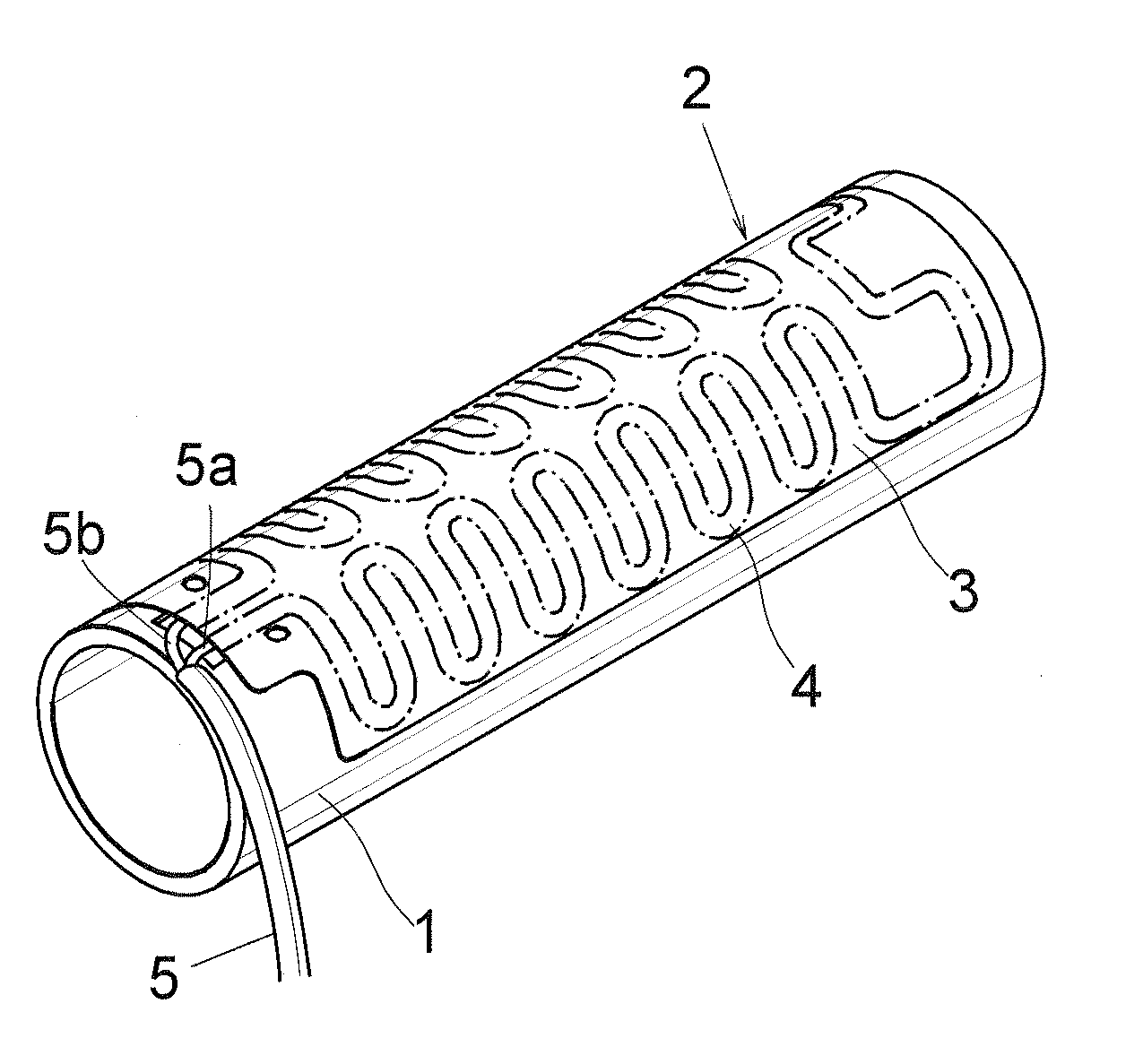
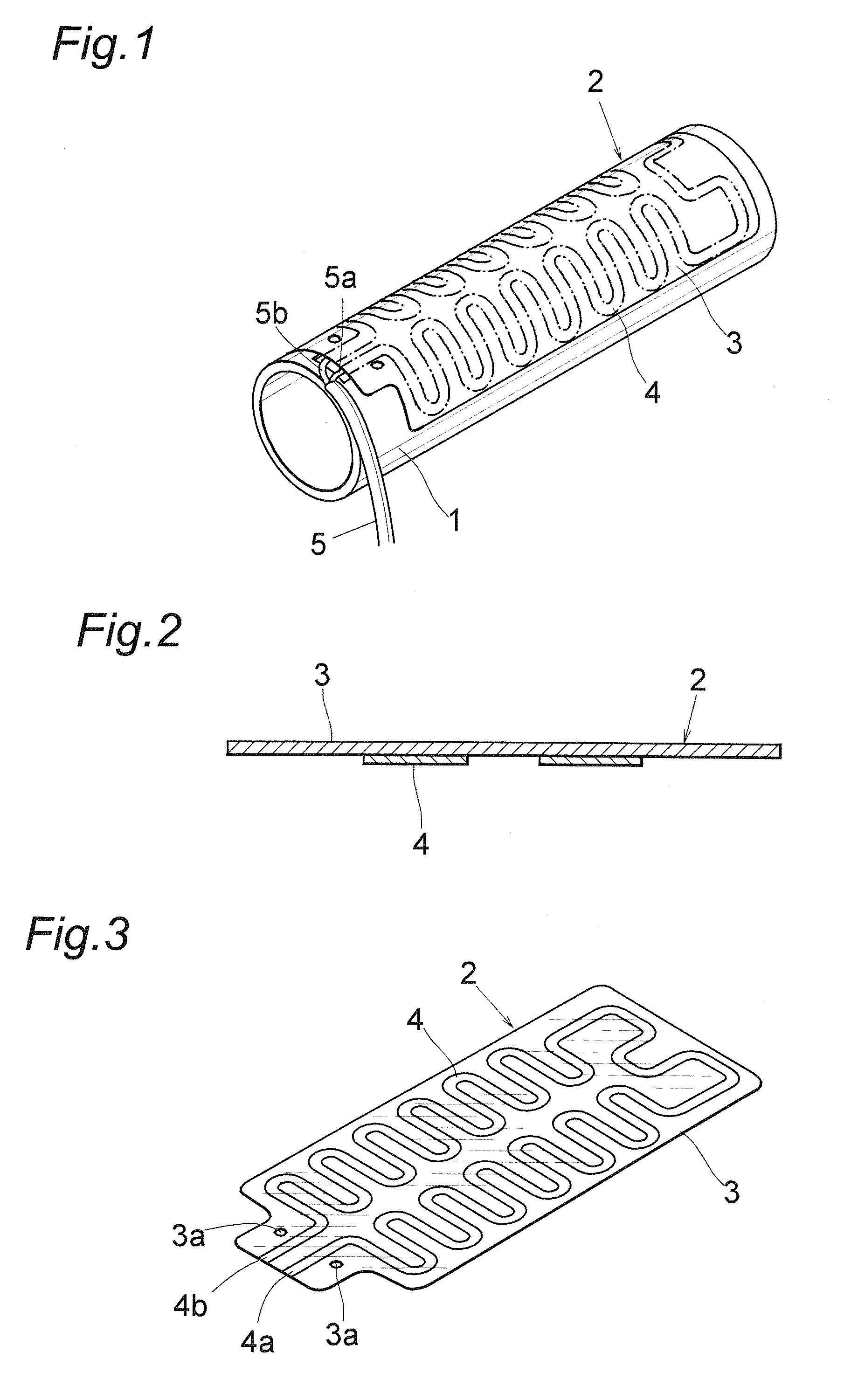
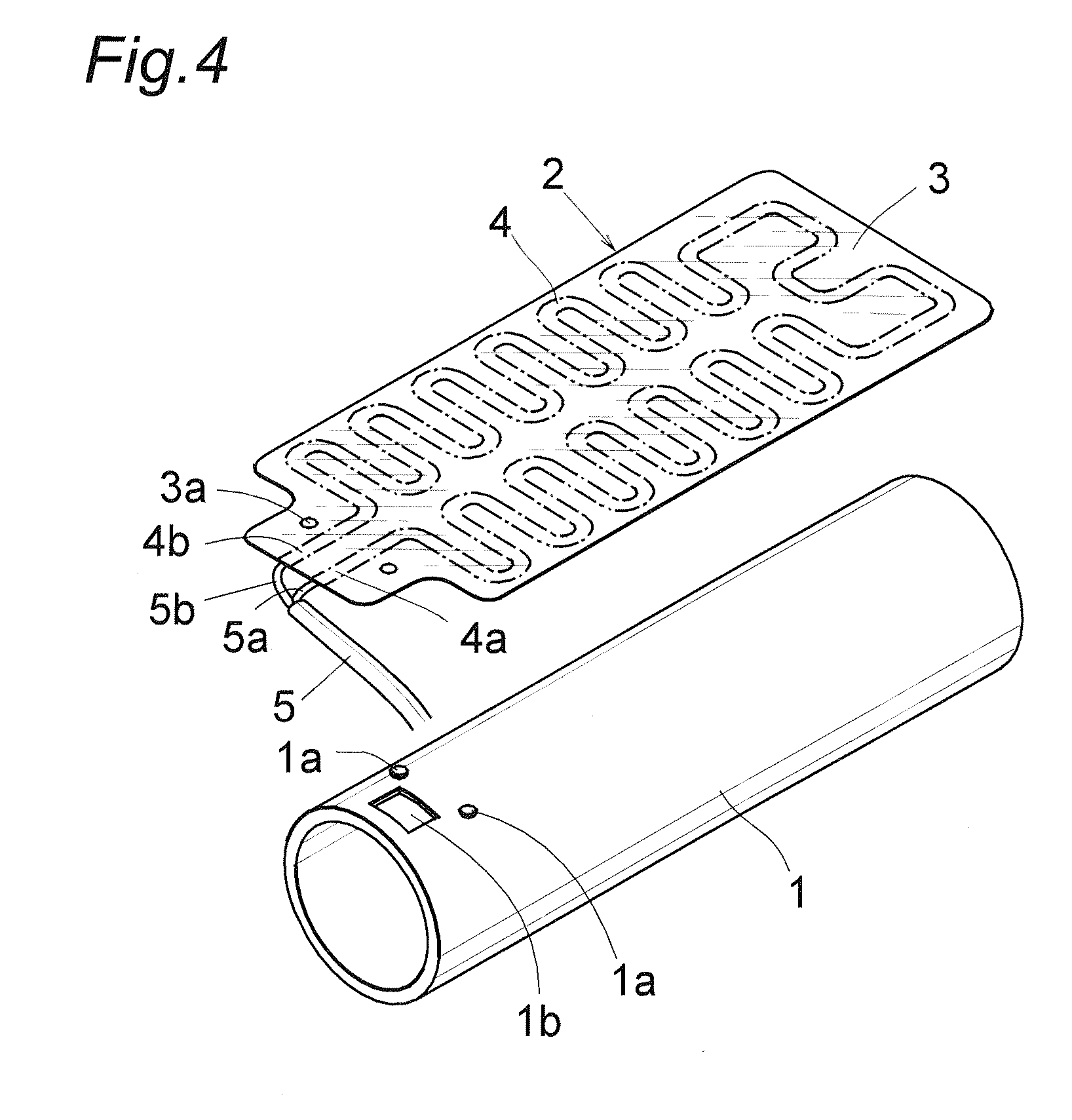
[0044]FIG. 1 is a perspective view showing a first embodiment 1 of the handle grip with heater according to the invention. On to a substantially half of an outer surface of a cylindrical core body 1 made of synthetic resin, a sheet-like heater unit 2 is adhered. As illustrated in FIG. 2, the heater unit 2 includes an electrically insulating and flexible insulating plate 3 made of synthetic resin and an electric resistance member 4 made of a metal foil, preferably SUS (stainless steel), is adhered with a suitable adhesive agent on a lower surface of the insulating plate 3. To both ends of the electric resistance member 4 are connected to mandrels 5a and 5b of an electric power supply wire 5 by welding or soldering.

[0045] The electric resistance member 4 is obtained in the following manner. At first a SUS foil is uniformly applied on the electrically insulating plate 3, the assembly of the insulating plate and SUS foil is half-punched to form the electric resistance member 4 having a...

embodiment 2

[0054]FIG. 11 is a perspective view showing a second embodiment 2. A core body 11 is formed as a semi-cylindrical shape and includes a ring-shaped portion 12 at a base end and a ring-shaped 13 at a free end, and a heater structure body 14 is adhered onto an outer surface of the core body 11.

[0055] As illustrated in FIG. 12, the heater structure body 14 is consisting of a sheet-like heater unit 15, a wire cover 16 and an electric power supply wire 17. Near both ends of the core body 11, there are formed heater holding projections 18 and a pair of supporting grooves 19 are formed at elongated outer edges of the core body 11 such that these supporting grooves are faced with each other to accommodate both ends of the heater unit 15. On outer surfaces of the ring-shaped portion 12 formed at the base end of the core body 11, there are formed stopping pieces 20 each having a stopping claw 20a for supporting the electric power supply wire 17.

[0056] The heater unit 15 has given size and sh...


PUM


Abstract

Onto a surface of a cylindrical core body 1 made of synthetic resin, is adhered a heater unit 2 which is formed by adhering, with an adhesive agent, an electric resistance member 4 made of a SUS foil on an inner surface of a flexible electrically insulating plate 3 made of synthetic resin. The electric resistance member 4 is formed by half-punching the SUS foil uniformly applied on the electrically insulating plate into a given configuration and removing an unnecessary portion. The electric resistance member 4 has a small width, a large length and a zigzag shape to increase electric resistance. Both ends of the electric resistance member constitute connecting portions for an electric power supply wire 5 and are arranged side by side at one end of the electrically insulating plate.

Description

[0001] The present application is Continuation-in-part of International Application PCT / 2005 / 000402 filed Jan. 14, 2005, the entire contents of which are incorporated by reference herein.FIELD OF THE INVENTION [0002] The present invention relates to a handle grip with heater for use in motorcycles and snowmobiles. BACKGROUND OF THE INVENTION [0003] In cold districts, handle grips with heater have been used for warming hands of users. There have been proposed known handle grips with heater which may be typically classified in the following two types: (1) as described in a Patent document 1, a plate-like heat generating member formed by applying electrically insulating sheets on both sides of an electrical heater made of copper or SUS like as FPC is adhered onto a cylindrical core body made of synthetic resin and a molded rubber body is formed on the heat generating member; and (2) a nichrome wire or SUS plate is applied on a synthetic resin core body and a molded rubber body is forme...

Claims


Application Information

Patent Timeline
Patent Type & Authority Applications(United States)
IPC IPC(8): B60L1/02B62J33/00B62K21/26H05B3/46
CPCB62J33/00H05B3/46B62K21/26
Inventor SASAKI, KOUZOUNAKAGAWA, CHIHIROAMBO, TSUGIONAKAYAMA, KIMIO
Owner HONDA ACCESS CORP
Why Eureka
Try Eureka