
A wireless synchronous trigger system and method for an optical tracking 3D scanner

A technology of optical tracking and synchronous triggering, applied in stereoscopic systems, optical devices, instruments, etc., can solve problems such as equipment disconnection, affecting the service life of equipment, wire movement and pulling interference, etc., and achieve the effect of improving the convenience of use

Active Publication Date: 2022-03-25
ZG TECH CO LTD
View PDF5 Cites 0 Cited by
  • Summary
  • Abstract
  • Description
  • Claims
  • Application Information

AI Technical Summary

Problems solved by technology

However, this wired connection method has many inconveniences in actual use. For example, in a factory environment, the site environment is relatively poor (even extremely harsh), and the connecting wire is very prone to wear and tear, and the moving and pulling of the wire is easy to interfere with Interference occurs in the on-site environment, and problems such as equipment disconnection occur, which seriously affect the service life of the equipment

Method used


Image

  • A wireless synchronous trigger system and method for an optical tracking 3D scanner
  • A wireless synchronous trigger system and method for an optical tracking 3D scanner
  • A wireless synchronous trigger system and method for an optical tracking 3D scanner

Examples


Embodiment

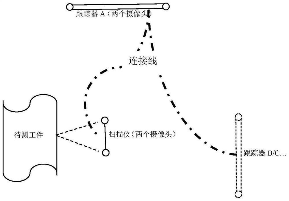
[0037] like Figure 4 As shown, an embodiment of the present invention provides a wireless synchronization trigger system for an optical tracking three-dimensional scanner. The system includes a master wireless synchronization device and a plurality of slave wireless synchronization devices that work in the same frequency band. The master wireless synchronization device and all The plurality of slave wireless synchronization devices are communicated and connected wirelessly. In the same space, there can be multiple wireless synchronization trigger systems working simultaneously in different wireless frequency bands.

[0038] The master wireless synchronization device first sends a PWM synchronization signal with a fixed frequency and duty cycle to the slave wireless synchronization device, and the slave wireless synchronization device automatically adjusts its output according to the PWM synchronization signal to ensure that both outputs are the same synchronization signal . ...


PUM


Abstract

The present invention relates to a wireless synchronization trigger system and method for an optical tracking three-dimensional scanner. The system includes a master wireless synchronization device and a plurality of slave wireless synchronization devices working in the same frequency band, and the master wireless synchronization device communicates with the scanner. The plurality of slave wireless synchronization devices communicate with the plurality of trackers in a one-to-one communication connection, and the master wireless synchronization device communicates with the plurality of slave wireless synchronization devices in a wireless manner. The master wireless synchronization device outputs a PWM synchronization signal with a fixed frequency and duty cycle to the scanner for triggering the scanner to work; the slave wireless synchronization device synchronously outputs the same PWM synchronization signal as the master wireless synchronization device to the scanner The corresponding tracker, used to trigger the tracker job. The application of wireless synchronization equipment solves the problem that the optical tracking 3D scanner needs a wired connection for synchronous trigger control, and greatly improves the convenience of using the optical tracking 3D scanner.

Description

technical field [0001] The invention relates to the fields of industrial photogrammetry, close-range photogrammetry and computer vision, in particular to a wireless synchronous triggering system and method for an optical tracking three-dimensional scanner. Background technique [0002] The technical basis of the 3D scanner is the principle of computer binocular vision, as shown in the appendix. figure 1 shown. If any point P in space is simultaneously imaged at points p1 and p2 by the left and right cameras at the same time, and the optical centers of the left and right cameras are O1 and O2 respectively, then the line connecting O1p1 and O2p2 will intersect at point P in space. Using the camera calibration method, the spatial positions of the optical centers O1 and O2 of the left and right cameras can be calculated, and then by extracting the image feature points p1 and p2 collected by the left and right cameras, the spatial point P in the world coordinate system Ow of the...

Claims


Application Information

Patent Timeline
Patent Type & Authority Patents(China)
IPC IPC(8): G01B11/24H04N13/239H04N13/296
CPCG01B11/24H04N13/239H04N13/296
Inventor 郑顺义周泽海王晓南成剑华刘庆龙
Owner ZG TECH CO LTD
Learn More