
Optimization method and system for insulation structure of converter transformer valve side sleeve outgoing line device

A converter transformer and insulation structure technology, applied in the field of electrical insulation, can solve problems such as complex structure, high tangential field strength of transformer oil, poor heat dissipation conditions, etc., and achieve the effect of optimization of insulation structure

Active Publication Date: 2020-08-28
WUHAN NARI LIABILITY OF STATE GRID ELECTRIC POWER RES INST +5
View PDF6 Cites 4 Cited by
  • Summary
  • Abstract
  • Description
  • Claims
  • Application Information

AI Technical Summary

Problems solved by technology

[0003] At present, the insulation structure of the bushing outlet device on the valve side of the converter transformer is divided into open type and closed type, among which: (1) The open type outlet structure has a simple insulation structure, which is beneficial to the flow of transformer oil and facilitates heat dissipation, and the electric field distribution in the barrier cardboard is relatively small. Reasonable, but the tangential field strength of the transformer oil along the surface of the insulation barrier is relatively high; (2) The closed outlet structure is composed of special-shaped barriers, the structure is relatively complex, the heat dissipation conditions are poor, and the electric field intensity in the normal direction it bears is relatively high , but the tangential electric field strength along the surface of the barrier in oil is small, which can prevent the surface flashover along the oil-paper interface

Method used


Image

  • Optimization method and system for insulation structure of converter transformer valve side sleeve outgoing line device
  • Optimization method and system for insulation structure of converter transformer valve side sleeve outgoing line device
  • Optimization method and system for insulation structure of converter transformer valve side sleeve outgoing line device

Examples


Embodiment Construction

[0037] In order to further explain the technical means and effects of the present invention to achieve the intended purpose of the invention, the specific implementation and structure according to the present invention will be described below in conjunction with the embodiment of the structure optimization of the bushing outlet device on the valve side of the ±800kV UHV converter transformer. , features and their effects are detailed as follows:

[0038] The invention discloses a method for optimizing the insulation structure of a bushing outlet device on a valve side of a converter transformer, comprising the following steps:

[0039] Apply the judgment matrix method to solve the weight of the pre-built optimization objective function;

[0040] Determine the optimal structural parameters of the insulation structure of the bushing outlet device on the valve side of the converter transformer based on the weights. This optimization method clarifies the importance of each optimiz...


PUM


Abstract

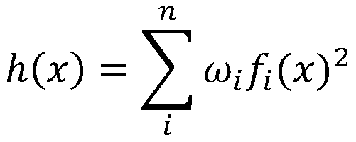
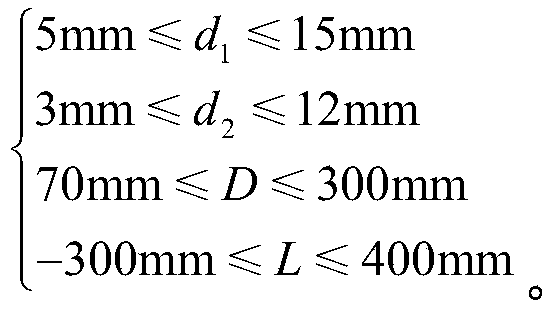
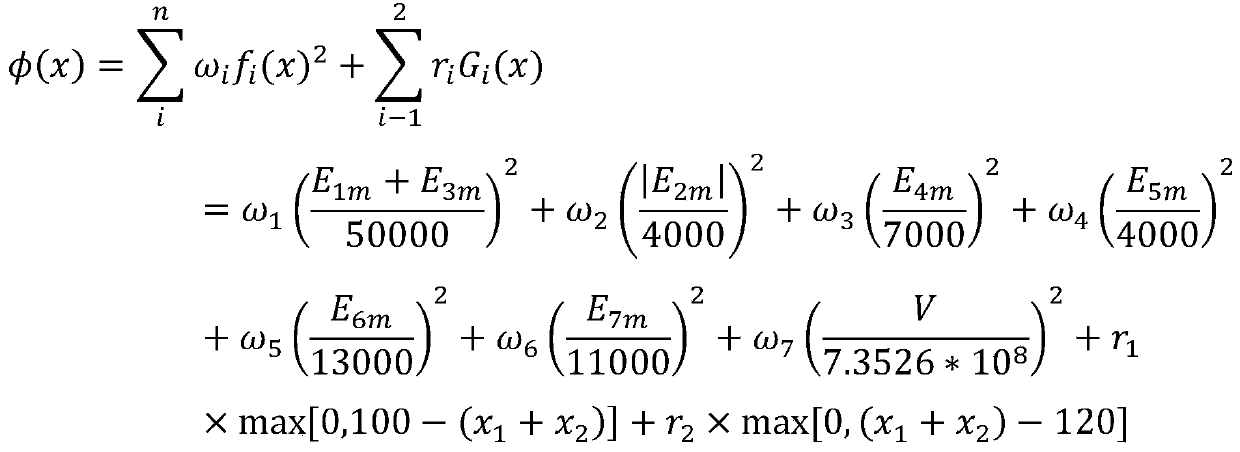
The invention discloses an optimization method of an insulation structure of a converter transformer valve side sleeve outgoing line device. The method comprises the steps of determining factors influencing the insulation structure of the converter valve side sleeve outgoing line device, constructing each optimization objective function based on the factors, constructing an evaluation function based on each optimization objective function, and synthesizing the evaluation function by using a penalty function and a constraint condition to obtain the insulation structure of the converter valve side sleeve outgoing line device; determining the weight of each optimization objective function and solving an unconstrained objective function; and obtaining insulation structure parameters and like of converter transformer valve side sleeve outgoing line device. According to the method, the importance of each optimization objective function is defined by constructing the optimization objective function of each optimization objective, so that the insulation structure of the converter transformer valve side bushing outgoing line device can be optimized.

Description

technical field [0001] The invention relates to the technical field of electrical insulation, in particular to a method and system for optimizing the insulation structure of a bushing outlet device on a valve side of a converter transformer. Background technique [0002] The insulation structure of the valve-side bushing outlet device of the converter transformer is an insulation device connecting the valve-side bushing and the converter transformer winding coil. Therefore, it is necessary to ensure that the insulation structure of the valve-side bushing outlet device has good electrical insulation performance. [0003] At present, the insulation structure of the bushing outlet device on the valve side of the converter transformer is divided into open type and closed type, among which: (1) The open type outlet structure has a simple insulation structure, which is beneficial to the flow of transformer oil and facilitates heat dissipation, and the electric field distribution in...

Claims


Application Information

Patent Timeline
Patent Type & Authority Applications(China)
IPC IPC(8): G06F30/17G06F30/23G06F111/06G06F111/04
CPCG06F30/17G06F30/23G06F2111/06G06F2111/04Y02E60/60
Inventor 邓建钢宋友徐卓林兰贞波柯磊聂宇彭宗仁
Owner WUHAN NARI LIABILITY OF STATE GRID ELECTRIC POWER RES INST
Learn More