Laser machining cooperation method, system, equipment and medium

A laser processing and working technology, applied in laser welding equipment, metal processing equipment, welding equipment and other directions, can solve the problems of repeated processing angle, boundary dislocation, limited laser processing size range, etc., to speed up processing and improve processing efficiency Effect

Inactive Publication Date: 2020-09-01
YANTAI MAGIC NANOTECHNOLOGY CO LTD
View PDF5 Cites 3 Cited by
  • Summary
  • Abstract
  • Description
  • Claims
  • Application Information

AI Technical Summary

Problems solved by technology

However, the current motion control equipment cannot meet the above three requirements at the same time.
Beam deflection equipment, such as high-speed galvanometers and diffraction deflection elements, can quickly adjust the position of the spot on the focal plane by controlling the angle of the outgoing beam. However, due to the limitation of the field of view of the focusing lens, the moving range of the focused spot, that is, the laser processing size range is limited. limit
[0003] In the prior art, if it is necessary to achieve a processing target larger than the field of view of the focusing lens, it is necessary to fix the material to be processed on the mechanical mobile platform, move the processed part out or partially out of the field of view of the lens, and place it in the new field of view. The graphics boundaries processed twice or more times are spliced ​​by machine vision or mechanical platform motion sensors, so as to realize laser processing larger than the field of view of the focusing lens, but multiple splicing will cause boundary misalignment, repeated processing and Angle deflection etc.

Method used


Image

  • Laser machining cooperation method, system, equipment and medium
  • Laser machining cooperation method, system, equipment and medium
  • Laser machining cooperation method, system, equipment and medium

Examples


Embodiment Construction

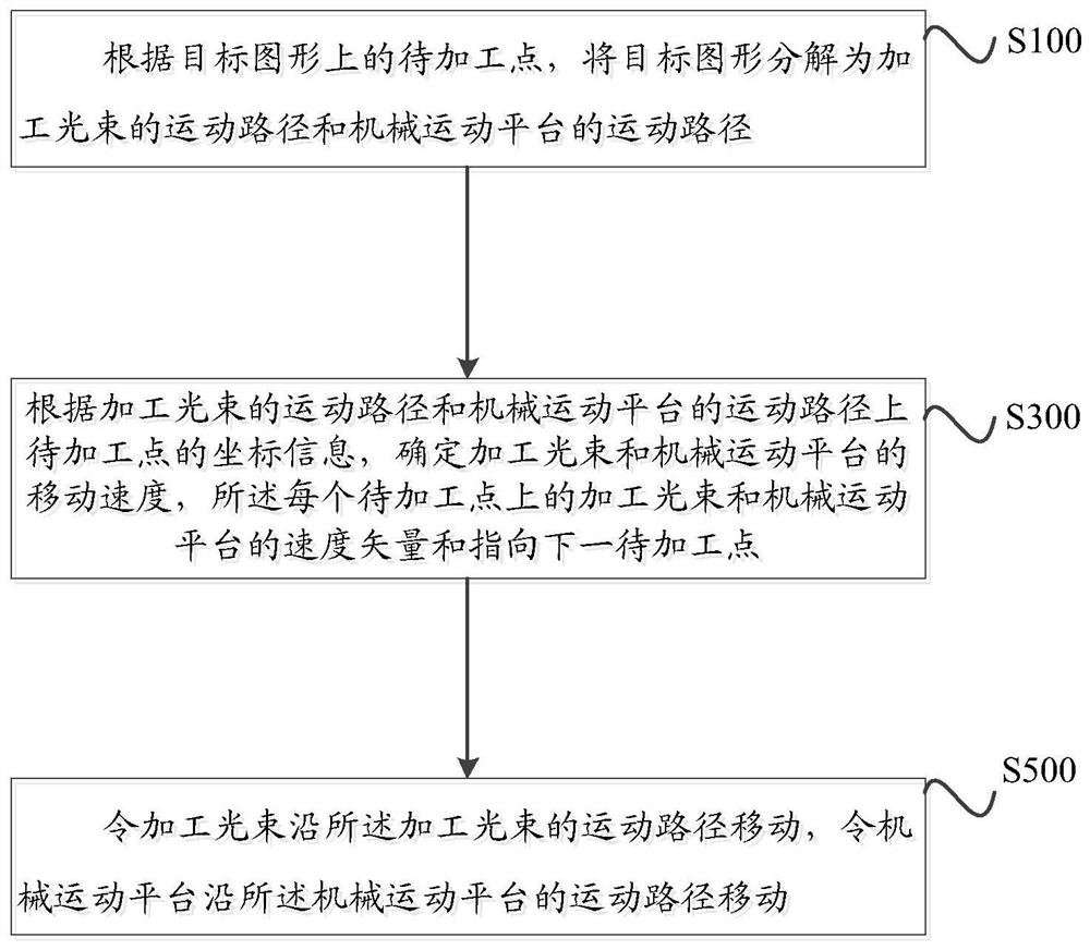
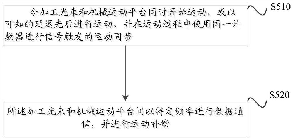
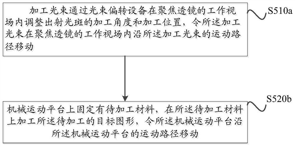
[0036] The core of the present invention is to provide a cooperative method, system, equipment and medium for laser processing that can control the processing beam and the mechanical motion platform to perform coordinated and cooperative movements, thereby reducing processing errors.

[0037] In order to enable those skilled in the art to better understand the solution of the present invention, the present invention will be further described in detail below in conjunction with the accompanying drawings and specific embodiments. Apparently, the described embodiments are only some of the embodiments of the present invention, but not all of them. Based on the embodiments of the present invention, all other embodiments obtained by persons of ordinary skill in the art without making creative efforts belong to the protection scope of the present invention.

[0038] The terms "first", "second", "third", "fourth", etc. (if any) in the specification and claims of the present applicatio...


PUM


Abstract

The invention discloses a laser processing cooperation method, system, equipment and a medium. The method comprises the following steps of decomposing a target graph into a movement path of a machining light beam and a movement path of a mechanical movement platform according to a to-be-processed point on the target graph; according to the motion path of the machining light beam and coordinate information of the to-be-machined point on the motion path of the mechanical motion platform, determining the moving speeds of the machining light beam and the mechanical motion platform; and enabling the machining light beam to move along the movement path of the machining light beam, and enabling the mechanical movement platform to move along the movement path of the mechanical movement platform. According to the laser machining cooperation method, system, the equipment and the medium, the target graph is decomposed point by point, the machining light beam and the mechanical motion platform match for machining, motion planning takes the whole target graph as a path, the machining light beam and the mechanical motion platform move in a continuous motion mode, and block division and splicingare not needed, so that the single-time machining range is not limited by a view field, and the problems of boundary dislocation, repeated machining, angle deflection and the like caused by splicing are solved.

Description

technical field [0001] The invention relates to the field of optical processing, in particular to a cooperative method, system, equipment and medium for laser processing. Background technique [0002] At present, laser processing and manufacturing technology is in a period of rapid development, and is developing towards higher precision, faster speed, and larger-scale processing. At the same time, this is also the development trend of the intelligent manufacturing industry and market demand. The existing laser processing process is usually realized by using the relative spatial movement between the focused laser spot and the material to be processed. This kind of relative movement is improved with high precision, high speed and large moving range. However, the current motion control equipment cannot meet the above three requirements at the same time. Beam deflection equipment, such as high-speed galvanometers and diffraction deflection elements, can quickly adjust the posit...

Claims


Application Information

Patent Timeline
Patent Type & Authority Applications(China)
IPC IPC(8): B23K26/00B23K26/08B23K26/70
CPCB23K26/00B23K26/0853B23K26/0876B23K26/705
Inventor 史强胡海龙周立海
Owner YANTAI MAGIC NANOTECHNOLOGY CO LTD
Why Eureka
Try Eureka