
Rear vehicle-body structure of vehicle

A body and vehicle technology, which is applied to the upper structure, lower structure, vehicle components, etc., can solve the problem of not being able to efficiently improve the rigidity of the rear of the body, and achieve the effect of improving the rigidity of the body

Active Publication Date: 2020-09-04
MAZDA MOTOR CORP
View PDF9 Cites 0 Cited by
  • Summary
  • Abstract
  • Description
  • Claims
  • Application Information

AI Technical Summary

Problems solved by technology

[0004] In the conventional technical solution disclosed in this patent document 1, an annular structural portion in the vehicle width direction is formed at the rear portion of the vehicle body, but the inner rear pillar reinforcement is separated from the shock absorber support portion of the rear suspension to the front side in the vehicle longitudinal direction. Therefore, the rigidity of the rear of the vehicle body cannot be improved efficiently, and there is still room for improvement in the rigidity of the rear of the vehicle body

Method used


Image

  • Rear vehicle-body structure of vehicle
  • Rear vehicle-body structure of vehicle
  • Rear vehicle-body structure of vehicle

Examples


Embodiment

[0043] An embodiment of the present invention will be described in detail below based on the accompanying drawings.

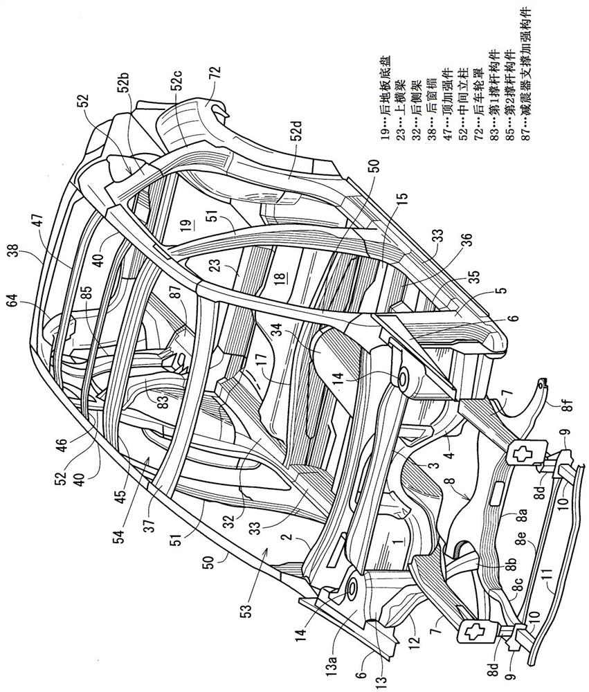
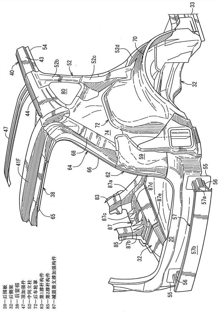
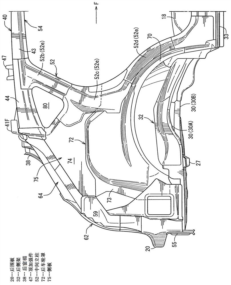
[0044] The accompanying drawings represent the rear body structure of the vehicle, figure 1 is a perspective view of the overall vehicle body structure including the rear body structure, and before describing the rear body structure, first refer to figure 1 The vehicle body structure on the front side of the vehicle will be described.

[0045] Such as figure 1 As shown, a dash panel 1 that separates the engine compartment and the cockpit in the front-rear direction of the vehicle is provided, and a dash top panel 2 is provided on the upper portion of the dash panel 1, and a front panel that connects the left and right sides in the vehicle width direction, which will be described later, is further provided in front of it. A closed cross-section extending in the vehicle width direction is formed between the dash cross member upper 3 of the suspension support po...


PUM


Abstract

The purpose of the present invention is to provide a rear vehicle body structure of a vehicle, the rear vehicle body structure being capable of reliably improving vehicle body rigidity at the rear ofthe vehicle by forming annular structural parts at the front and rear of a damper support part of a rear suspension. The rear vehicle body structure of the vehicle is provided with a shock absorber supporting part of a rear suspension and includes a first annular structure part (Z1) which is annular in the vehicle width direction and a second annular structure part (Z2) which is annular in the vehicle width direction. The first annular structure part (Z1) is arranged in front of the shock absorber supporting part, so that a vehicle body lower wall part (H), left and right side wall parts (I) and an upper wall part (J) are continuous. The second annular structure part (Z2) is arranged behind the shock absorber supporting part, so that the vehicle body lower wall part (K), the left and rightside wall parts (L) and the upper wall part (M) are continuous. The first and second annular structural parts are each formed by a closed cross-sectional part formed by a reinforcing member or by a thick plate part having a plate thickness greater than that of a vehicle body plate.

Description

technical field [0001] The present invention relates to a rear body structure of a vehicle in which a ring-shaped structural portion in the vehicle width direction is formed at the rear of the vehicle body by a closed cross section or a thick plate portion thicker than the body plate. Background technique [0002] Conventionally, Patent Document 1 discloses a rear vehicle body structure of a vehicle exemplified below. [0003] That is to say, this technical solution is: the shock absorber support part of the rear suspension is provided on the upper part of the rear wheel house; The rear pillar reinforcement and the outer rear pillar reinforcement form a closed section of the left and right side walls extending in the vertical direction, and the roof and the roof reinforcement form a closed section of the upper wall extending in the vehicle width direction. In the rear part of the vehicle body, a ring-shaped structural part that connects the above closed cross-sectional part...

Claims


Application Information

Patent Timeline
Patent Type & Authority Applications(China)
IPC IPC(8): B62D25/08B62D25/04B62D25/16B62D25/02B62D21/15B62D25/20
CPCB62D25/088B62D25/04B62D25/16B62D25/025B62D21/157B62D25/20B62D25/087B62D25/02B60G2204/128B62D21/11B62D21/155B62D25/08
Inventor 清下大介西村佳和中村岳司
Owner MAZDA MOTOR CORP
Learn More