
Press-formed article, press-forming method, and press-forming apparatus

a press-forming method and press-forming technology, applied in the field of press-forming, can solve the problems of low flexibility of design of the floor cross member, and the difficulty of conventional press-forming methods to enable cold forming of the continuous outward flange b>4/b> including the curving section,

Active Publication Date: 2021-10-21
NIPPON STEEL CORP
View PDF0 Cites 0 Cited by
  • Summary
  • Abstract
  • Description
  • Claims
  • Application Information

AI Technical Summary

Benefits of technology

This patent describes a method for making a press-formed article that can be joined to other members, increasing rigidity and load transfer characteristics. By using an outward flange formed from the edge portion of the top sheet portion, the edge portion of the convex ridge line portion, the edge portion of the sidewall, and the edge portion of the concaved ridge line portion as a joint margin, the press-formed article can be joined to other members. This improves bending rigidity and twisting rigidity of the automobile body shell and increases steering stability, riding comfortableness, and noise reduction. Additionally, the method allows for the formation of the outward flange using shearing deformation, without the need for a cutout to prevent fracture and wrinkles.

Problems solved by technology

However, formability of the high-tensile strength steel sheet is not good, and therefore, it is a problem that a flexibility of design of the floor cross member 1 is low.
Accordingly, the cold forming of the continuous outward flange 4 including the curving section 4a tends to be difficult to be enabled by the conventional press-forming method.

Method used


Image

  • Press-formed article, press-forming method, and press-forming apparatus
  • Press-formed article, press-forming method, and press-forming apparatus
  • Press-formed article, press-forming method, and press-forming apparatus

Examples


embodiment 1

(1) Embodiment 1

1. Press-Formed Article 10 According to the Present Embodiment

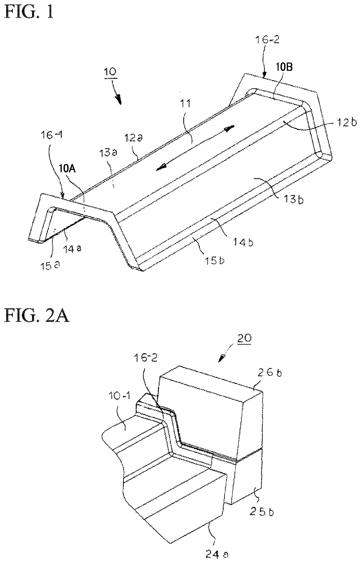
[0106]FIG. 1 is a perspective view showing a press-formed article 10 according to the present embodiment.

[0107]The press-formed article 10 shown in FIG. 1 is a press-formed article formed from a high-tensile strength steel sheet (sheet thickness: 0.6 to 3.5 mm) having a tensile strength of not less than 390 MPa, preferably not less than 590 MPa, and more preferably not less than 980 MPa.

[0108]The press-formed article 10 has a substantially hat type cross section including a top sheet portion 11, two convex ridge line portions 12a, 12b, two sidewalls 13a, 13b, and two concaved ridge line portions 14a, 14b, and two flanges 15a, 15b.

[0109]In this cross section, two convex ridge line portions 12a, 12b are both continuing to the top sheet portion 11. Each of the two sidewalls 13a, 13b continues to each of the two convex ridge line portions 12a, 12b. Each of the two concaved ridge line portions 14a, 14b continu...

embodiment 2

(2) Embodiment 2

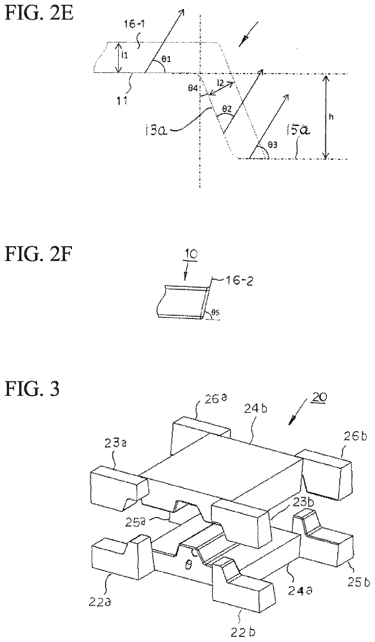
[0160]In FIG. 8A to FIG. 23 which are referred to in the following explanation, with respect to the punch and the die, reference numbers are assigned such as first punch 24a-1, first die 24b-1, second punches 22a-1 to 3, 22b-1 to 3, 25a-1 to 3, 25b-1 to 3, and second dies 23a-1 to 3, 23b-1 to 3, 26a-1 to 3, 26b-1 to 3. The difference of the number assigned after the symbol “-” means that merely the outer surface shape of the punch or the inner surface shape of the die is modified.

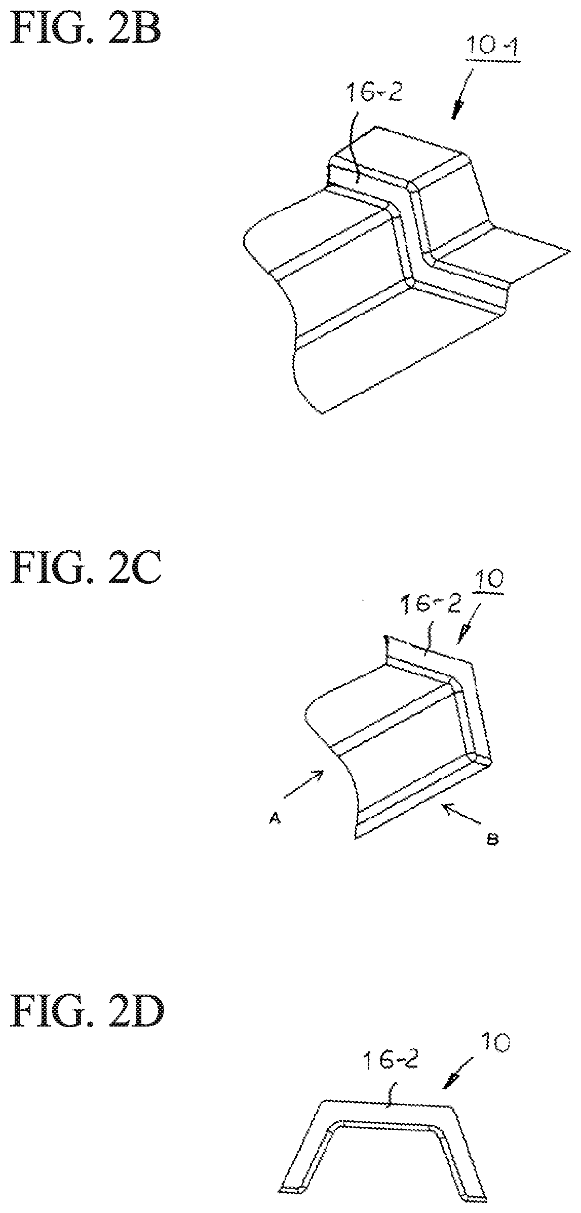
[0161]FIG. 8A to FIG. 8F are explanatory views showing an overview of a state where an intermediate formed article 10-3 of the press-formed article 10 is manufactured by using a press-forming apparatus 20-1 according to this embodiment. FIG. 8A is a perspective view showing a main part of the press-forming apparatus 20-1 after forming the stepped portion 16-2 which becomes the outward flange. FIG. 8B is a perspective view showing a main part of the intermediate formed article 10-3 formed wit...

embodiment 3

(3) Embodiment 3

[0180]FIG. 14 is a perspective view showing the press-formed article 10 according to the present embodiment.

[0181]FIG. 15 is an explanatory view showing an overview of a state where an intermediate formed article 10-5 of the press-formed article 10 is manufactured by using a press-forming apparatus 20-2 according to this embodiment.

[0182]FIG. 15A is a perspective view showing a main part of the press-forming apparatus 20-2 after forming the stepped portion 16-2 which becomes the outward flange.

[0183]FIG. 15B is a perspective view showing a main part of the intermediate formed article 10-5 formed with the stepped portion 16-2. FIG. 15C is a perspective view showing an area in the vicinity of the outward flange 16-2 of the press-formed article 10. FIG. 15D is an A-arrow view in FIG. 15C. FIG. 15E is a B-arrow view in FIG. 15C.

[0184]FIG. 16 is a perspective view showing members of the press-forming apparatus 20-2 according to this embodiment.

[0185]FIG. 17 is an explanat...


PUM


Abstract

This press-formed article includes: a top sheet portion; a sidewall continuing to the top sheet portion via a convex ridge line portion; a flange continuing to the sidewall via a concaved ridge line portion; and an outward flange continuing from an edge portion of the top sheet portion to an edge portion of the flange, via an edge portion of the convex ridge line portion, an edge portion of the sidewall, and an edge portion of the concaved ridge line portion, wherein in the same unit, an average thickness TAve, a minimum thickness TMin, and a maximum thickness TMax of the outward flange satisfy Equation 1 and Equation 2.0.8×TAve≤TMin<TAve   (Equation 1)TAve<TMax≤1.2×TAve   (Equation 2)

Description

TECHNICAL FIELD[0001]The present invention relates to a press-formed article excellent in rigidity and strength, which is suitably used for automotive body reinforcement member, and relates to a press-forming method and a press-forming apparatus.[0002]This application is a Divisional of co-pending Application No. 15 / 576,187, filed on Nov. 21, 2017, which is the National Phase under 35 U.S.C. § 371 of International Application No. PCT / JP2016 / 066238, filed on Jun. 1, 2016, which claims priority under 35 U.S.C. § 119(a) to Japanese Patent Application No. 2015-111436, filed in Japan on Jun. 1, 2015, all of which are hereby expressly incorporated by reference, in their entirety, into the present application.BACKGROUND ART[0003]A floor of an automobile vehicle body (hereinafter, simply referred to as “floor”) is not only primary responsible for torsional rigidity and bending rigidity of the vehicle body when the vehicle travels, but also responsible for transfer of an impact load when a c...

Claims


Application Information

Patent Timeline
Patent Type & Authority Applications(United States)
IPC IPC(8): B21D28/26B21D22/02B21D24/16B21D22/20B21D22/26B21D53/88
CPCB21D28/26B21D22/02B21D53/88B21D22/20B21D22/26B21D24/16B21D5/01B62D25/20
Inventor TANAKA, YASUHARUOGAWA, MISAOMIYAGI, TAKASHIASO, TOSHIMITSUTANOUE, HIROYUKIKURODA, RYO
Owner NIPPON STEEL CORP
Learn More