
Radio frequency equipment

A technology of radio frequency equipment and radio frequency signals, applied in the direction of waveguides, circuits, electrical components, etc., can solve the problems of impossible and disadvantageous conductive connection

Inactive Publication Date: 2020-09-04
ALCAN SYST GMBH
View PDF7 Cites 0 Cited by
  • Summary
  • Abstract
  • Description
  • Claims
  • Application Information

AI Technical Summary

Problems solved by technology

However, for some applications and devices, such a conductive connection is not possible or considered disadvantageous

Method used


Image

  • Radio frequency equipment
  • Radio frequency equipment
  • Radio frequency equipment

Examples


Embodiment Construction

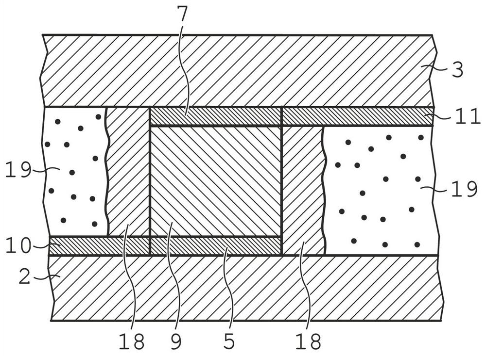
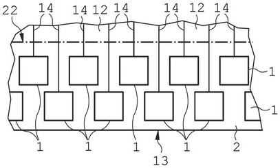
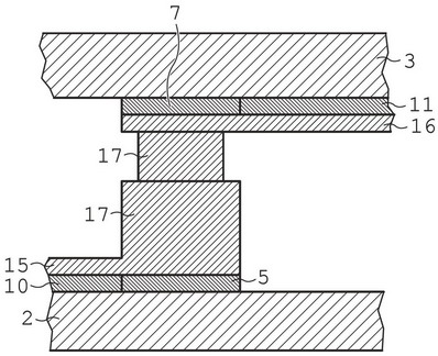
[0036] figure 1 A cross-sectional view of a first embodiment of a conductive intersection 1 between a first substrate layer 2 and a second substrate layer 3 of a radio frequency device 4 is shown. The conductive intersection 1 between the first and second substrate layers 2, 3 comprises a first intersecting electrode 5 arranged on the first surface 6 of the first substrate layer 2 and a second electrode arranged on the second substrate layer 3. Second interdigitated electrodes 7 on surface 8 . The two substrate layers 2 , 3 are arranged parallel and with the first surface 6 of the first substrate layer 2 facing the second surface 8 of the second substrate layer 3 . Both substrate layers 2, 3 are made of glass.

[0037] The volume between the first intersecting electrodes 5 and the second intersecting electrodes 7 is filled with an electrically conductive material 9 providing an electrically conductive connection between the first intersecting electrodes 5 and the second inte...


PUM


Abstract

The invention provides radio frequency equipment (4), which comprises a first substrate layer (2) and a second substrate layer (3) arranged at a distance from each other, wherein the first and secondsubstrate layers (2, 3) comprise electrically conductive transmission line elements (10, 11, 10', 11'') on the first surface (6) of the first substrate layer (2) and on the second surface (8) of the second substrate layer (3), the electrically conductive transmission line elements allow radio frequency signals to be transmitted in a transmission direction, the radio frequency equipment (4) furthercomprises more than one electrically conductive crossing part (1) between the first surface (6) of the first substrate layer (2) and the second surface (8) of the second substrate layer (3), the electrically conductive crossing part provides electrically conductive connection of the respective electrically conductive transmission line elements (10, 11) on the first and second substrate layers (2,3), at least one phase shift region (12) of the radio frequency equipment (4) comprises corresponding regions of respective first and second substrate layers (2, 3) for forming at least one radio frequency phase shift element arranged on the first and second substrate layers (2, 3), all electrically conductive crossing parts (1) are arranged outside the at least one phase shift region (12) of theradio frequency equipment (4), and each electrically conductive crossing part (1) is electrically connected to a respective phase shift element.

Description

technical field [0001] The invention relates to a radio frequency device comprising a first substrate layer and a second substrate layer arranged at a distance towards each other, wherein the first and second substrate layers comprise a first substrate layer and a second substrate layer on a first surface of the first substrate layer. a conductive transmission line element on the second surface of the second substrate layer, which allows the transmission of radio frequency signals along a transmission direction defined by the transmission line element parallel to the first surface of the first substrate layer or parallel to the second surface of the second substrate layer, And the radio frequency device has a conductive crossover between the first surface of the first substrate layer and the second surface of the second substrate layer, which provides a connection between the conductive transmission line element on the first surface of the first substrate layer and the second ...

Claims


Application Information

Patent Timeline
Patent Type & Authority Applications(China)
IPC IPC(8): H01P3/08
CPCH01P3/08
Inventor O.H.卡拉贝
Owner ALCAN SYST GMBH
Learn More