
Stamping equipment for socket inserts

A technology of stamping equipment and inserts, applied in the field of stamping equipment for socket inserts, which can solve problems such as inability to push sideways, difficult layout, and drop of inserts, and achieve the effects of avoiding interference, improving production efficiency, and increasing reliability

Inactive Publication Date: 2020-09-08
杭州银湖机械弹簧有限公司
View PDF0 Cites 2 Cited by
  • Summary
  • Abstract
  • Description
  • Claims
  • Application Information

AI Technical Summary

Problems solved by technology

After stamping in the last process, the stamping insert is generally more complicated. During stamping, it cannot be directly punched in the last stamping process, and because there is a lower die in the last process, even after punching, due to the existence of the lower die The punched inserts cannot fall by gravity; therefore, for general equipment, the final punching process and discharge process are not combined with the stamping process; if they can be combined, the stamping efficiency will be improved
[0004] According to the existing design ideas, a side pusher is added in the last stamping process. After the final stamping and punching is completed, the insert is pushed out from the side through the side pusher. However, as mentioned above, after the last process is completed, the insert It is generally more complicated and cannot be pushed out sideways; further analysis according to the existing thinking, the insert piece can be lifted first, and then pushed sideways; but there will be a large demand for the space on the upper side of the lower mold; There is a certain space on the side, which is not easy to arrange in practice; therefore, considering the small space on the upper side of the lower die, how to combine the final stamping process, punching process and discharge process is very necessary.

Method used


Image

  • Stamping equipment for socket inserts
  • Stamping equipment for socket inserts
  • Stamping equipment for socket inserts

Examples


Embodiment Construction

[0042] The specific implementation manners of the present invention will be further described in detail below in conjunction with the accompanying drawings and embodiments. The following examples or drawings are used to illustrate the present invention, but not to limit the scope of the present invention.

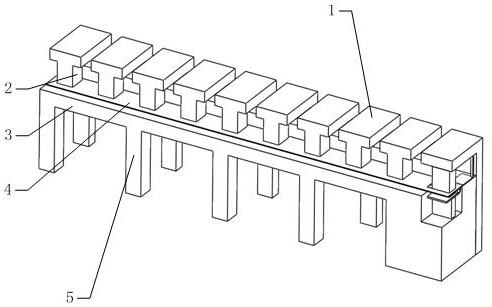
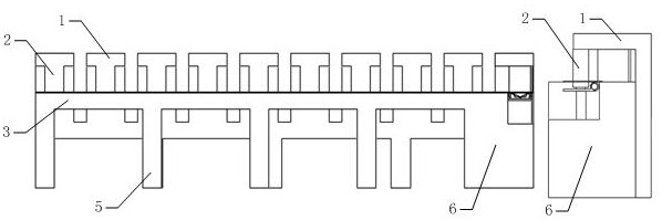
[0043] Such as figure 1 , 2 As shown, it includes an upper mold control module 1, an upper mold 2, a workbench 3, a support 5, and a lower mold 7, wherein the workbench 3 is installed on the upper side of the support 5, and the upper side of the workbench 3 has evenly distributed lower molds 7; The upper mold control module 1 is installed on the rear side of the workbench 3, such as figure 1 , 10 As shown, multiple upper molds are evenly installed on the upper mold control module 1, and the upper mold 2 installed on the upper mold control module 1 and the lower mold 7 on the upper side of the workbench 3 cooperate with each other to form a plurality of different worksta...


PUM


Abstract

The invention belongs to the technical field of stamping, and particularly relates to stamping equipment for socket inserts. The equipment comprises an upper die control module, an upper die, a workbench and a lower die. The stamping equipment is characterized in that a metal sheet is stamped into a specified shape on previous stations, when the metal sheet passes through the last station, the metal sheet finishes final stamping, punching is carried out while the final stamping is completed, and finally a punched stamping part is discharged by means of the gravity of the stamping part when theswing angle of a swing plate is larger than 90 degrees. According to the stamping equipment, a final stamping procedure, a final punching procedure and a final discharging procedure can be combined together on the last station, and the production efficiency is improved.

Description

[0001] Technical field [0002] The invention belongs to the technical field of punching, and in particular relates to a punching device for socket inserts. Background technique [0003] Socket inserts are generally stamped in multiple processes. After the last stamping process is completed, they are punched and then discharged through the guide plate. After stamping in the last process, the stamping insert is generally more complicated. During stamping, it cannot be directly punched in the last stamping process, and because there is a lower die in the last process, even after punching, due to the existence of the lower die The punched inserts cannot fall by gravity; therefore, for general equipment, the final punching process and discharge process are not combined with the stamping process; if they can be combined, the stamping efficiency will be improved. [0004] According to the existing design ideas, a side pusher is added in the last stamping process. After the final st...

Claims


Application Information

Patent Timeline
IPC IPC(8): B21D35/00B21D37/08B21D45/08
CPCB21D35/002B21D37/08B21D45/08
Inventor 潘俐邵文宇董淑文
Owner 杭州银湖机械弹簧有限公司
Features
  • Generate Ideas
  • Intellectual Property
  • Life Sciences
  • Materials
  • Tech Scout
  • Unparalleled Data Quality
  • Higher Quality Content
  • 60% Fewer Hallucinations
Learn More