Spool loading and unloading transport vehicle

An I-shaped wheel and transport vehicle technology, which is applied in the directions of transportation and packaging, reel unit transportation, vehicle parts, etc., can solve the problems of increasing manufacturing costs, device dumping, and easy damage to the I-shaped wheel, etc., so as to save manufacturing costs and reduce Configuration requirements, the use of flexible and convenient effects

Active Publication Date: 2020-09-08
ZHENGZHOU RES INST OF MECHANICAL ENG CO LTD
View PDF10 Cites 2 Cited by
  • Summary
  • Abstract
  • Description
  • Claims
  • Application Information

AI Technical Summary

Problems solved by technology

[0004] The above-mentioned transportation device allows the I-shaped wheel to realize the transfer during rolling. The I-shaped wheel directly contacts and rubs against the ground, which is easy to damage the I-shaped wheel. Of course, it can also completely lift the I-shaped wheel off the ground through the lifting mechanism, but this is necessary for lifting The power configuration requirements of the mechanism are relatively high, and because the two side walls of the U-shaped piece are overhanging, the requirements for the strength of the U-shaped piece itself and the connection strength with the lifting mechanism are relatively high. The center of gravity is relatively forward, and the whole device is at risk of tipping over
In addition, since the telescopic drive mechanism is installed horizontally and outside the two side walls of the U-shaped piece, the lateral dimension of the entire transport device is relatively large. During the transfer process, sufficient lateral passing space is required, and the scope of application is limited, or some very inconvenient to use

Method used


Image

  • Spool loading and unloading transport vehicle
  • Spool loading and unloading transport vehicle
  • Spool loading and unloading transport vehicle

Examples


Embodiment Construction

[0037] In order to make the object, technical solution and advantages of the present invention clearer, the present invention will be further described in detail below in conjunction with the accompanying drawings and embodiments. It should be understood that the specific embodiments described here are only used to explain the present invention, and are not intended to limit the present invention, that is, the described embodiments are only some of the embodiments of the present invention, but not all of the embodiments. The components of the embodiments of the invention generally described and illustrated in the figures herein may be arranged and designed in a variety of different configurations.

[0038] Accordingly, the following detailed description of the embodiments of the invention provided in the accompanying drawings is not intended to limit the scope of the claimed invention, but merely represents selected embodiments of the invention. Based on the embodiments of the p...


PUM


Abstract

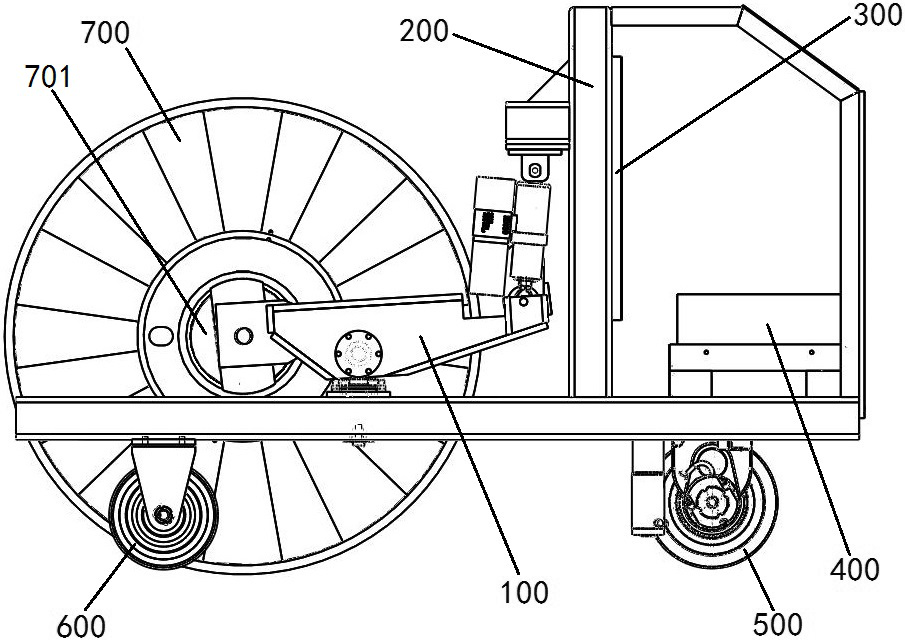
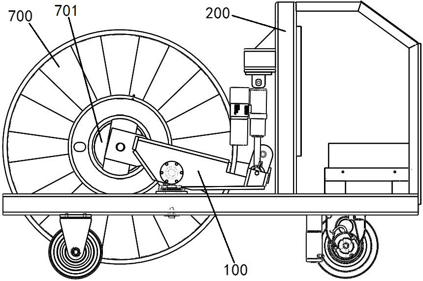
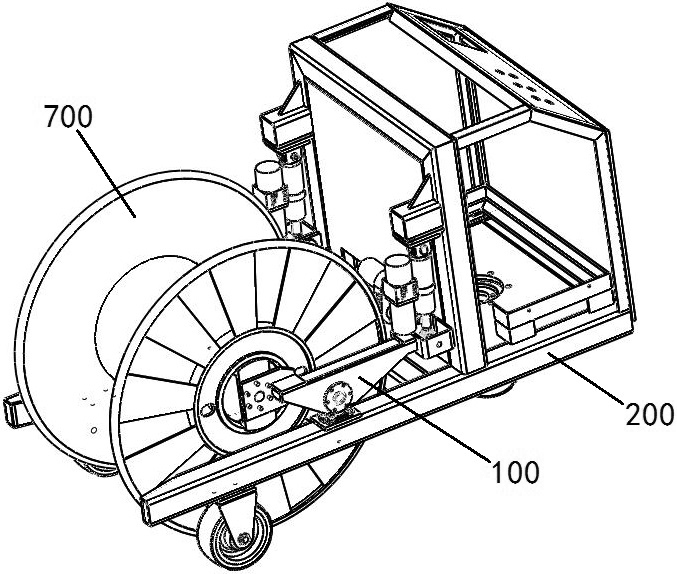
The invention provides a spool loading and unloading transport vehicle which comprises a frame comprising two longitudinal beams and a stand column; two clamping arms which are respectively arranged on each longitudinal beam; a clamping power mechanism which is connected with the rear ends of the two clamping arms; two lifting power mechanisms which are vertically arranged at the rear ends of theclamping arms correspondingly, and are connected between the stand column and the rear ends of the clamping arms; the clamping arms are mounted on the longitudinal beams through a composite mounting structure to form a lever structure taking the composite mounting structure as a fulcrum; the composite mounting structure comprises a vertical rotating shaft and a horizontal rotating shaft, the clamping arms rotate around the vertical shaft under the action of the clamping power mechanism to achieve opening and closing, and the clamping arms rotate around the horizontal shaft under the action ofthe lifting power mechanisms to achieve lifting and falling. The clamping arms are controlled to act according to the lever principle, the labor-saving purpose can be achieved, the configuration requirement for a power mechanism is lowered, and the manufacturing cost is saved. The clamping power mechanism is located between the two clamping arms, the outer side space is not occupied, the transverse size is small, and use is flexible and convenient.

Description

technical field [0001] The invention relates to an I-shaped wheel loading and unloading transport vehicle. Background technique [0002] In the production process of wire products such as wire and cable, steel wire rope, welding wire, etc., the turnover of semi-finished products often uses I-shaped wheels as carrying tools. Most of the loading and unloading of the I-shaped wheel on the take-up or pay-off equipment is manual loading and unloading. The manual loading and unloading of the I-shaped wheel is labor-intensive and low in production efficiency. I-wheels use common forklifts and other transportation equipment in the turnover transportation process. In order to reduce labor intensity and improve production efficiency, a kind of I-wheel loading and unloading transportation equipment that can be loaded and unloaded and transported is needed. [0003] In this regard, the Chinese invention patent application with the application publication number of CN110775881A disclose...

Claims


Application Information

Patent Timeline
Patent Type & Authority Applications(China)
IPC IPC(8): B60P3/035B62D21/09
CPCB60P3/035B62D21/09
Inventor 李五田高建立刘伟常守亮陈生超王艺菲孙毅博夏营侯耐王宽儒
Owner ZHENGZHOU RES INST OF MECHANICAL ENG CO LTD
Why Eureka
Try Eureka