Positioning and cutting device for use in processing of decorative plates and using method

A technology for positioning cutting and decorating plates, which is applied to feeding devices, metal processing equipment, metal processing machinery parts, etc., can solve problems such as troubles, and achieve the effects of simple operation, good use convenience, and convenient adjustment

Active Publication Date: 2020-09-11
安徽省汇金木业股份有限公司
View PDF10 Cites 2 Cited by
  • Summary
  • Abstract
  • Description
  • Claims
  • Application Information

AI Technical Summary

Problems solved by technology

[0003] In the production process of architectural decorative panels, the cutting process is one of the more important processes. When cutting the panels, the existing architectural decorative panel cutting devices cannot realize arc-shaped cutting of the panels, and often need to rely on CNC processing machinery. Therefore, it will be more troublesome during processing, so we propose a positioning cutting device and method of use for processing decorative panels to solve the above-mentioned problems

Method used


Image

  • Positioning and cutting device for use in processing of decorative plates and using method
  • Positioning and cutting device for use in processing of decorative plates and using method
  • Positioning and cutting device for use in processing of decorative plates and using method

Examples


Embodiment 1

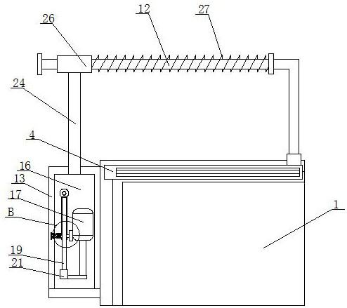
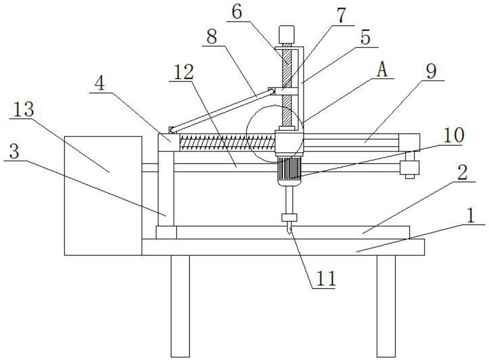
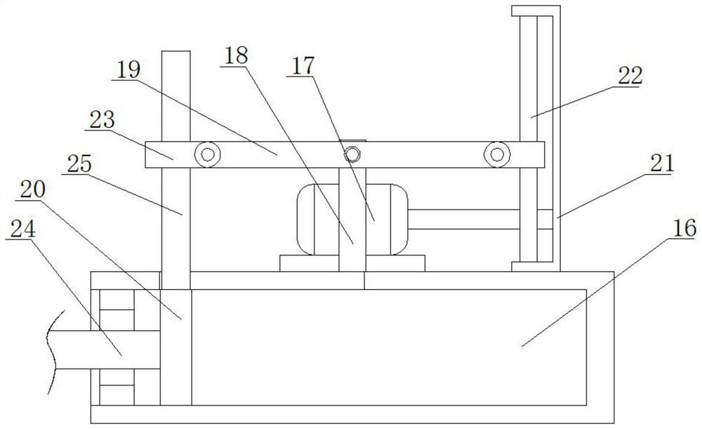
[0030] see Figure 1-5 , this embodiment provides a positioning and cutting device for processing decorative panels, including a workbench 1, an L-shaped positioning plate 2 is fixedly installed on the top of the workbench 1, and a support rod 3 is rotatably connected to one side of the top of the workbench 1, The top of the support rod 3 is fixedly equipped with a support ring 4, and the support ring 4 is slidably connected with a moving ring 14. The bottom of the moving ring 14 extends to the bottom of the support ring 4 and is fixedly installed with a cutting motor 10, and the output shaft of the cutting motor 10 A milling cutter 11 is fixedly installed on the top, the top of the moving ring 14 extends to the top of the support ring 4 and a mounting frame 5 is fixedly mounted on it, and a nut 7 is threaded on the mounting frame 5, and one side of the nut 7 is rotatably connected to a transmission rod 8 , one end of the transmission rod 8 is rotationally connected to the top...


PUM


Abstract

The invention discloses a positioning and cutting device for use in processing of decorative plates and a using method. The positioning and cutting device comprises a workbench, wherein an L-shaped positioning plate is fixedly arranged on the top of the workbench; a support rod is rotationally connected to one side of the top of the workbench; a support ring is fixedly arranged at the top end of the support rod; a movable ring is connected in the support ring in a sliding way; the bottom of the movable ring extends to the lower part of the support ring, and a cutting motor is fixedly arrangedat the bottom of the movable ring; a milling cutter is fixedly arranged on an output shaft of the cutting motor; and the top of the movable ring extends to the upper part of the support ring, and a mounting frame is fixedly arranged on the top of the movable ring. According to the positioning and cutting device, the cutting motor can be pulled to perform arc motion by starting an electric push rod, so that the milling cutter can be driven to perform arc motion in order to fulfill the aim of cutting arc shapes on the decorative plates. In addition, the motion radius of the cutting motor can beadjusted conveniently in order to adapt to arc cutting of various sizes conveniently. Meanwhile, the positioning and cutting device is relatively easy to operate, so that great convenience is broughtto use.

Description

technical field [0001] The invention relates to the related technical field of plate processing machinery, in particular to a positioning cutting device for processing decorative plates and a method for using it. Background technique [0002] Architectural decoration is the abbreviation of architectural decoration engineering. Architectural decoration is to protect the main structure of the building, improve the physical performance of the building, use functions and beautify the building. Architectural decoration is an indispensable part of people's life. It is an important friend of human beings who taste life and taste life, and plays an important role in people's life. [0003] In the production process of architectural decorative panels, the cutting process is one of the more important processes. When the existing architectural decorative panel cutting devices are used to cut the panels, they cannot achieve arc-shaped cutting of the panels, and often need to rely on CNC...

Claims


Application Information

Patent Timeline
Patent Type & Authority Applications(China)
IPC IPC(8): B23C3/00B23C9/00B23Q5/28
CPCB23C3/00B23C9/00B23Q5/28
Inventor 王艳王建孝陈云超
Owner 安徽省汇金木业股份有限公司
Why Eureka
Try Eureka