Switching circuit and printer using method applying switching circuit

A technology for switching circuits and printers, applied in printing devices, electronic switches, printing, etc., can solve problems such as the inability to realize the multiplexing function of switch buttons, and achieve the effects of saving costs, reducing difficulty, and reducing the amount of settings

Pending Publication Date: 2020-09-11
NINGBO DELI KEBEI TECH CO LTD
View PDF1 Cites 1 Cited by
  • Summary
  • Abstract
  • Description
  • Claims
  • Application Information

AI Technical Summary

Problems solved by technology

Most of these switch buttons use mechanical fixed buttons, such as boat switches, button switches, and self-locking switches. The switch buttons need to be placed in a separate operating position and only have the function of power on and off, and cannot realize the multiplexing function of the switch buttons. use

Method used


Image

  • Switching circuit and printer using method applying switching circuit
  • Switching circuit and printer using method applying switching circuit

Examples


Embodiment 1

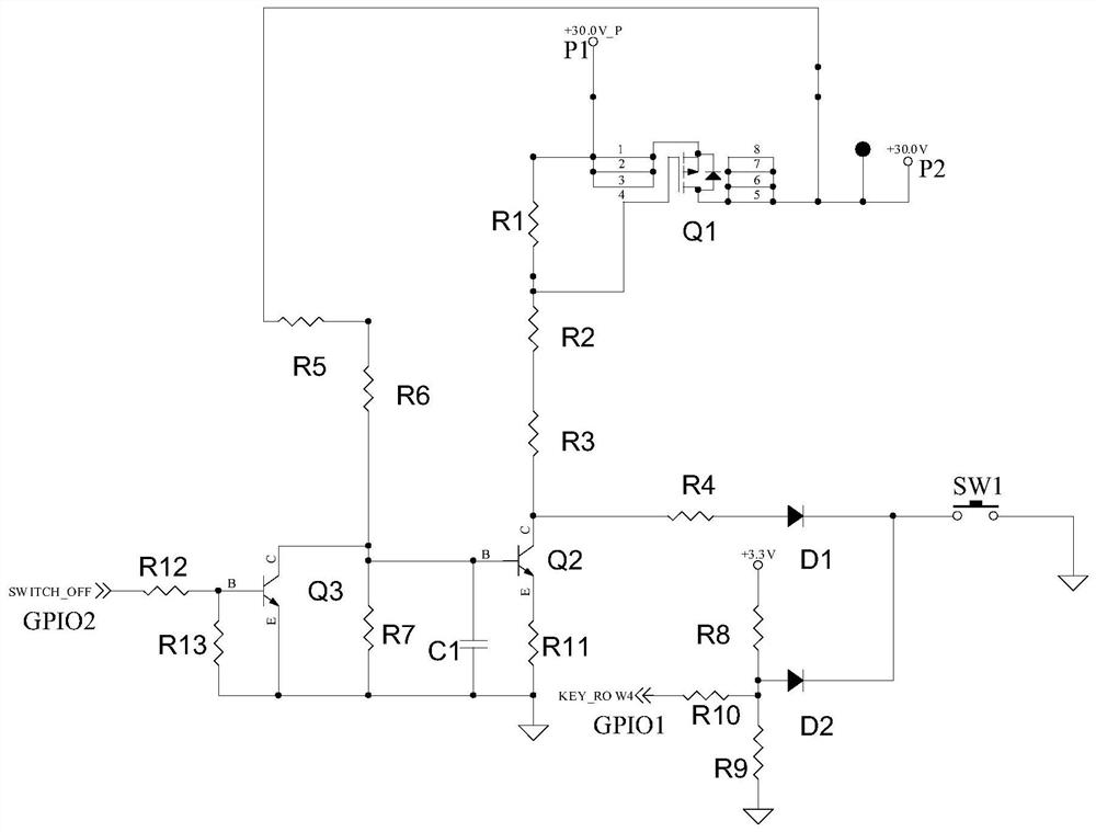
[0033] Such as figure 1 As shown, the switch circuit in this embodiment includes a start-up module Q1, a button SW1, a hold module Q2, a turn-off module Q3, and a control module. A special hold module Q4 can be selected according to the load condition.

[0034] The power-on module Q1 is electrically connected to the power supply and the load to be powered, and is used for powering on and conducting the circuit. If the switching circuit is applied to a printer, the output terminal of the power-on module Q1 is electrically connected to the power supply terminal of the functional circuit board in the printer.

[0035] The button SW1 can adopt various buttons SW1 in the prior art. The button SW1 in this embodiment is a tact switch. When in use, the button SW1 is operated to realize on / off and multiplexing functions.

[0036] The holding module Q2 is electrically connected to the button SW1 and the starting module Q1 respectively, and is used to keep the switching on of the startin...

Embodiment 2

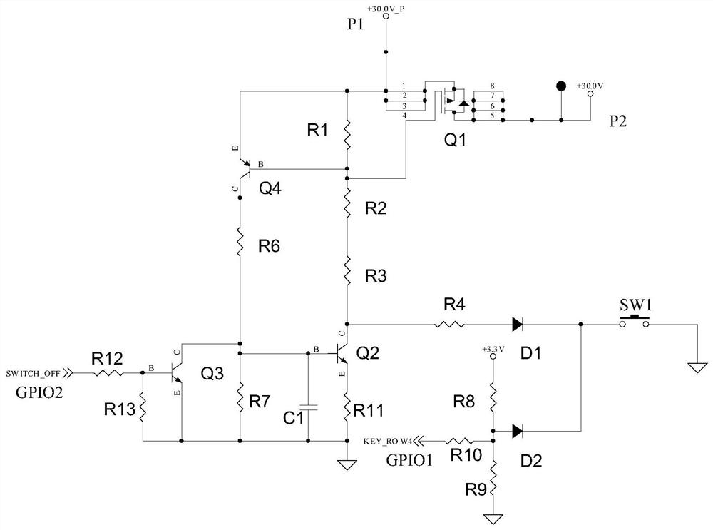
[0056] Such as figure 2 As shown, the difference between this embodiment and Embodiment 1 is that if there is an inductive device in the load to be powered, and the output load is too inductive, the current cannot be cut off in time when the power is turned off. In order to complete the cut-off, a special holding module Q4 can be set , while not setting the fifth resistor R5 or disconnecting the electrical connection between the fifth resistor R5 and the drain of the PMOS transistor. The special holding module Q4 is electrically connected to the starting module Q1, the holding module Q2, and the shutdown module Q3. The special holding module Q4 cooperates with the holding module Q2 to realize the state that the starting module Q1 is kept on or off.

[0057] The special holding module Q4 includes a PNP transistor, the base of the PNP transistor is electrically connected to the second end of the first resistor R1, the emitter of the PNP transistor is electrically connected to t...


PUM


Abstract

The invention relates to a switching circuit which comprises: a starting-up module which is electrically connected with a power supply and is used for electrifying and switching on the circuit; a keywhich is operated to be used for realizing startup and shutdown and multiplexing functions; a maintaining module which is electrically connected with the key and the startup module and is used for maintaining the conduction of the startup module; a shutdown module which is electrically connected with the holding module and is used for powering off the startup module; and a control module which iselectrically connected with the key and the shutdown module and is used for controlling to output a multiplexing function signal or a shutdown signal according to the detected key signal. The switching circuit can perform switching operation and reuse of various functions through one key, so that the product is simple in structure and low in cost. The invention further relates to a using method ofthe printer. The printer applies the switching circuit. By operating the keys, startup and shutdown and function reuse of the printer are realized. The using method of the printer is simpler and moreconvenient to operate.

Description

technical field [0001] The invention relates to a switch circuit, and also relates to a printer using the switch circuit. Background technique [0002] Printers are widely used in offices and homes. Existing printers are usually provided with a plurality of keys for controlling different functions, such as an on / off key specially used for on / off operation of the printer, and a function key used for It is used to realize the control of different functions of the printer. For example, the authorized announcement number is CN210634282U (application number is 201920914389.9) Chinese utility model patent "A High-precision Thermal Printer", in which the disclosed printer is specially set with the switch button corresponding to the switch circuit, and the switch circuit receives the switch The key switch signal output by the key is used to control the switch of the printer. Most of these switch buttons use mechanical fixed buttons, such as boat switches, button switches, and self...

Claims


Application Information

Patent Timeline
IPC IPC(8): H03K17/96H03K17/567B41J29/393
CPCB41J29/393H03K17/567H03K17/96
Inventor 竺宗光
Owner NINGBO DELI KEBEI TECH CO LTD
Why Eureka
Try Eureka