Contactless radial position sensor having improved response behavior to target defects
A non-contact, electromagnetic sensor technology, applied in the direction of converting sensor output, using electric/magnetic devices to transmit sensing components, instruments, etc., can solve problems such as rotor bumpy motion, magnetic bearings do not expect control signals, etc., and achieve easy interference signals Effect
- Summary
- Abstract
- Description
- Claims
- Application Information
AI Technical Summary
Problems solved by technology
Method used
Image


Examples
no. 1 approach
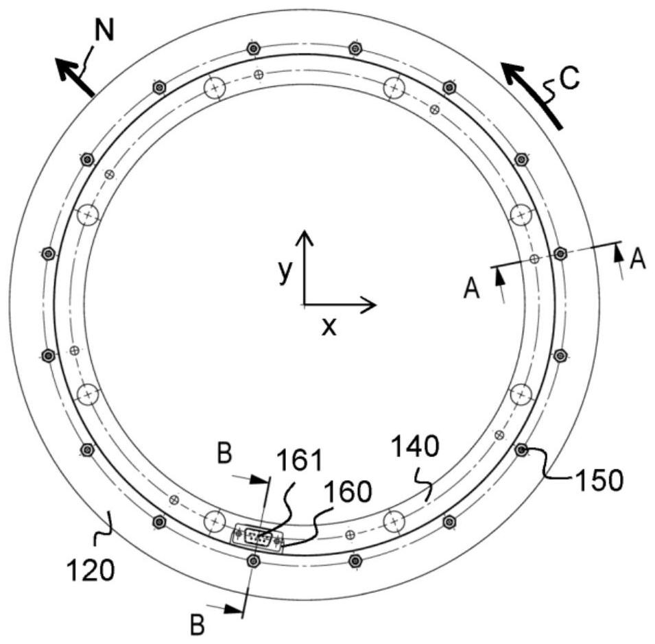
[0073] The transducer assembly 1 according to the first embodiment of the invention is Figure 1 to Figure 5 Shown in the figure. The transducer assembly 1 is configured to define a hollow outer rotor radially surrounding the transducer assembly 1 (not in Figure 1 to Figure 5 The radial position shown in the figure). Thus, the transducer assembly 1 is configured to interact with a target surface on the inner circumference of the hollow rotor.
[0074] The transducer assembly 1 includes a first transducer 100 and a second transducer 100'. Each transducer 100, 100' includes a loop coil support 110, 110'. The loop coil supports 110, 110' define a common longitudinal axis L ( image 3 ). At one axial end, the transducer assembly 1 comprises a conductive annular base plate 120 . The transducers 100, 100' are separated by a conductive shield ring 130. At the other axial end of the transducer assembly, the transducer assembly includes a conductive annular top plate 140 ....
no. 2 approach
[0106] Figure 16A transducer unit 1' according to a second embodiment of the invention is illustrated. The transducer unit 1' of the second embodiment is very similar to the transducer unit 1 of the first embodiment. However, the outer circumference of the second transducer 100' is covered by an annular, metallic reference target 180 arranged at a fixed radial distance from the first and second coils of the second transducer 100'. distance. In order to accommodate the reference target 180, the coil support of the second transducer has a slightly reduced outer diameter compared to the coil support of the first transducer.
[0107] exist Figure 17 A possible application of the transducer unit 1' with the second embodiment is illustrated in a highly schematic manner in . Similar parts are used with Figure 15 denoted by the same reference numerals. Again, for simplicity, rotor 300 is illustrated as an inner rotor, but rotor 300 could also be an outer rotor. In this embod...
no. 3 approach
[0111] will refer to Figure 18 A transducer according to a third embodiment will be described. While the first and second embodiments are designed to interact with an outer rotor, the third embodiment is designed to be used with an inner rotor.
[0112] In general, it is easier to implement the invention with an external rotor. In this case, the coil interacts radially outward with the target. The coils can be arranged in the slots from the outside and will be held by the hooks of the coil support without any other measures. This is not the case when the transducer is designed to interact with the internal rotor. In this case, specific measures need to be taken to avoid the coils falling inside and touching the inner rotor. Therefore, it is proposed to also mount the coil to the coil support from the outside, similarly to the first and second embodiments. The coil is then filled with resin, and the coil support is turned from the inside until only a thin film remains bet...
PUM
 Abstract
Description
Claims
Application Information
 - R&D
- Intellectual Property
- Life Sciences
- Materials
- Tech Scout
- Unparalleled Data Quality
- Higher Quality Content
- 60% Fewer Hallucinations
Browse by: Latest US Patents, China's latest patents, Technical Efficacy Thesaurus, Application Domain, Technology Topic, Popular Technical Reports.
© 2025 PatSnap. All rights reserved.Legal|Privacy policy|Modern Slavery Act Transparency Statement|Sitemap|About US| Contact US: help@patsnap.com