
Limb rehabilitating bracket for rehabilitation department

A technology of limbs and brackets, which is applied in the field of limb rehabilitation brackets, can solve the problems of limbs not fixed, the length and joint angle cannot be adjusted, and the lifting of the bracket can only raise the lower limbs, etc., to achieve enhanced stability, easy adjustment and adjustable The effect of the position of the fixing strap

Inactive Publication Date: 2020-09-15
石门县瑞升工程有限公司
View PDF8 Cites 5 Cited by
  • Summary
  • Abstract
  • Description
  • Claims
  • Application Information

AI Technical Summary

Problems solved by technology

[0002] For patients with limb fractures or limb surgery, during the early treatment period, when the patient is resting in bed, the affected limb needs to be raised. Elevating the patient plays an important role in promoting the venous and lymphatic return of the lower limbs to eliminate tissue edema. At present, Thomas racks are often used clinically. Pillows, sponges, pillows, etc. raise the affected limbs, but the horse stand is not flexible when used, and the length and angle of each joint cannot be adjusted. , can not reach the effective height and the purpose of braking the limbs, etc., and the general lifting bracket can only raise the lower limbs, and the lifting function of the upper limbs is not involved, so that patients with fractures of both upper and lower limbs are very difficult to recover in bed. It is difficult to take into account the upper limbs. Therefore, a bracket that has the rehabilitation function of raising the upper and lower limbs, can easily adjust the joint angle, and makes the patient more comfortable has great market value.

Method used


Image

  • Limb rehabilitating bracket for rehabilitation department
  • Limb rehabilitating bracket for rehabilitation department

Examples


Embodiment

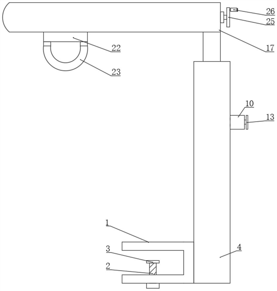
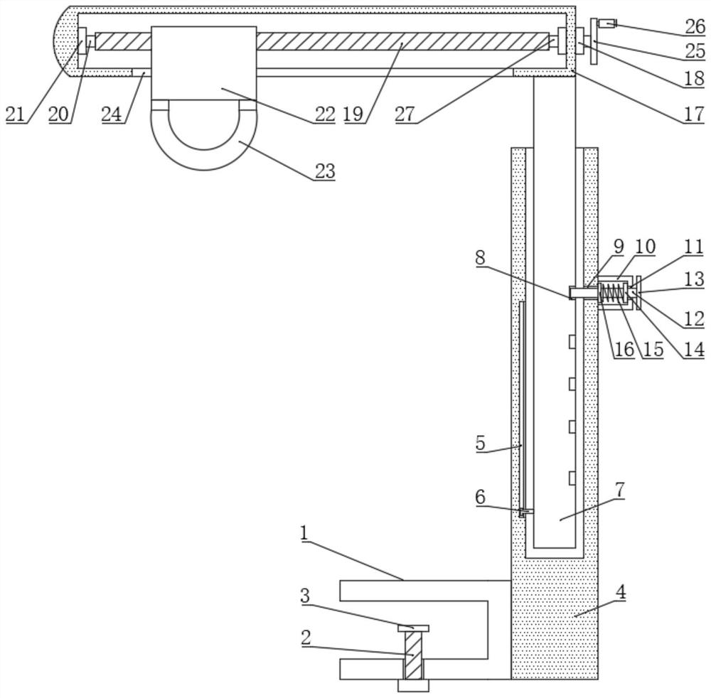
[0015] see Figure 1-2 , the present invention provides the following technical solutions: a limb rehabilitation bracket used in the rehabilitation department, including a block 1, the surface of the block 1 is pierced with a screw 2, and the upper surface of the screw 2 is fixedly connected with a non-slip pad 3, By setting the clamping block 1, the screw 2 and the anti-skid pad 3, when fixing the device, people clamp the clamping block 1 on the designated position of the bed body, and then tighten the screw 2, and then fix the position of the device , under the action of the block 1, the screw 2 and the anti-slip pad 3, it is more convenient for people to fix the position of the device, and at the same time, under the action of the anti-slip pad 3, the stability of the device is enhanced, and the surface of the block 1 A sleeve 4 is fixedly connected, and the inner wall of the sleeve 4 is provided with a chute 5, and a slider 6 is movably connected in the chute 5, and the su...


PUM


Abstract

The invention belongs to the technical field of medical treatment instruments, and particularly relates to a limb rehabilitating bracket for a rehabilitation department. The limb rehabilitating bracket comprises a clamping block, wherein a screw penetrates into the surface of the clamping block, a slid-proof pad is fixedly connected to the upper surface of the screw, a sleeve is fixedly connectedto the surface of the clamping block, a sliding chute is formed in the inner wall of the sleeve, a sliding block is movably connected in the sliding chute, a first sliding rod is fixedly connected tothe surface of the sliding block, and a plurality of clamping slots are formed in the surface of the first sliding rod. By arranging the clamping block, the screw and the slid-proof pad, the clampingblock is clamped to an appointed position of a bed body by a user when the device is fixed, the screw is screwed down by the user, and then the position of the device is fixed, so that the position ofthe device can be advantageously fixed by the user under the effects of the clamping block, the screw and the slid-proof pad, and meanwhile, the stability of the device is improved under the effect of the slid-proof pad.

Description

technical field [0001] The invention belongs to the technical field of medical devices, and in particular relates to a limb rehabilitation bracket used in the rehabilitation department. Background technique [0002] For patients with limb fractures or limb surgery, during the early treatment period, when the patient is resting in bed, the affected limb needs to be raised. Elevating the patient plays an important role in promoting the venous and lymphatic return of the lower limbs to eliminate tissue edema. At present, Thomas racks are often used clinically. Pillows, sponges, pillows, etc. raise the affected limbs, but the horse stand is not flexible when used, and the length and angle of each joint cannot be adjusted. , can not reach the effective height and the purpose of braking the limbs, etc., and the general lifting bracket can only raise the lower limbs, and the lifting function of the upper limbs is not involved, so that patients with fractures of both upper and lower...

Claims


Application Information

Patent Timeline
Patent Type & Authority Applications(China)
IPC IPC(8): A61G7/075
CPCA61G7/0755A61G2210/10
Inventor 盛达成
Owner 石门县瑞升工程有限公司
Learn More