
Material taking device

A technology of reclaiming device and mounting plate, which is applied in the directions of transportation and packaging, conveyor objects, etc., can solve the problem that the end of the manipulator is easy to shake, etc.

Inactive Publication Date: 2020-09-18
ZHUHAI GREE INTELLIGENT EQUIP CO LTD +1
View PDF7 Cites 0 Cited by
  • Summary
  • Abstract
  • Description
  • Claims
  • Application Information

AI Technical Summary

Problems solved by technology

[0005] The main purpose of the present invention is to provide a pick-up device to solve the problem in the prior art that the end of the manipulator with the pick-up device is easily shaken

Method used


Image

  • Material taking device
  • Material taking device
  • Material taking device

Examples


Embodiment Construction

[0029] It should be noted that, in the case of no conflict, the embodiments in the present application and the features in the embodiments can be combined with each other. The present invention will be described in detail below with reference to the accompanying drawings and examples.

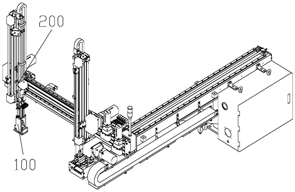
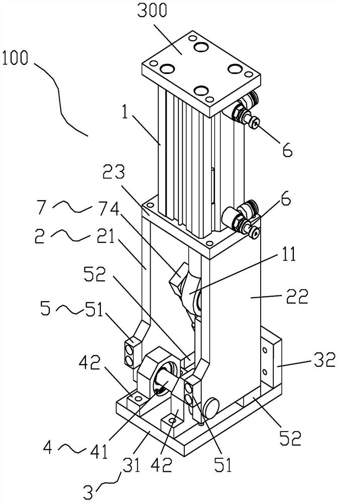
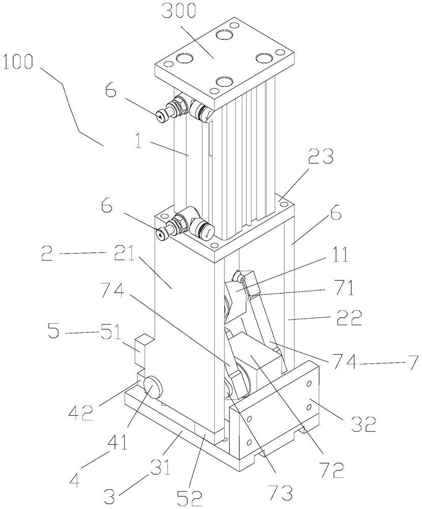
[0030] Such as Figure 1 to Figure 9 As shown, the present invention provides a kind of material retrieving device, has clamp mounting plate 3, and material retrieving device also comprises: support frame 2; Drive piston cylinder 1, drive piston cylinder 1 is installed on the support frame 2, drive piston cylinder 1 and The clamp mounting plate 3 is driven and connected to drive the clamp mounting plate 3 to the first position or the second position by driving the piston cylinder 1; the positioning assembly 4, the positioning assembly 4 includes a rotating shaft 41, and the rotating shaft 41 is installed on the support frame 2; The positioning assembly 4 is connected to the clamp mounting plat...


PUM


Abstract

The invention mainly aims at providing a material taking device which is provided with a clamp installation plate. The material taking device further comprises a supporting frame, a drive piston cylinder, a positioning assembly and a buffering assembly. The drive piston cylinder is installed on the supporting frame and is in drive connection with the clamp installation plate so that the clamp installation plate can be driven through the drive piston cylinder to move to the first position or the second position. The positioning assembly comprises a rotating shaft which is installed on the supporting frame. The positioning assembly is connected with the clamp installation plate so that the clamp installation plate can be rotationally arranged around the axis of the rotating shaft to rotate to the first position or the second position. The buffering assembly is provided with a first buffering part and a second buffering part, the first buffering part corresponds to the first position, thesecond buffering part corresponds to the second position, and therefore the first buffering part and the second buffering part can be used for buffering the clamp installation plate. According to thematerial taking device, the problem that a mechanical hand tail end provided with the material taking device is likely to jitter in the prior art is solved.

Description

technical field [0001] The invention relates to the technical field of injection molding machine production, in particular to a material reclaiming device. Background technique [0002] In the prior art, the end of the finished arm of the injection molding manipulator is designed with a retrieving device, and the molded workpiece in the mold of the injection molding machine is taken out through the clamp installed on the retrieving device. [0003] The reclaiming device has two motion postures in the horizontal direction and the vertical direction, and most of the existing reclaiming devices are driven by cylinders (a few reclaiming devices are driven by motors) to realize the switch between the two motion postures, and the speed of the reclaiming device is determined by The flow rate of the compressed air is determined, and it is impossible to adjust the movement speed of the reclaiming device independently. When the two motion postures are switched, the reclaiming device ...

Claims


Application Information

Patent Timeline
IPC IPC(8): B29C45/42B65G47/90
CPCB29C45/42B65G47/902
Inventor 黄建威陈瑜若代国龙钟文涛吴信宜张天翼
Owner ZHUHAI GREE INTELLIGENT EQUIP CO LTD
Learn More