
Unmanned aerial vehicle lighting equipment

A lighting equipment and unmanned aerial vehicle technology, applied in the field of lighting, can solve the problems of lighting mechanism shaking, insufficient battery life, and restrictions on the use range of lighting equipment

Inactive Publication Date: 2020-09-18
GUANGDONG POWER GRID CO LTD +1
View PDF8 Cites 1 Cited by
  • Summary
  • Abstract
  • Description
  • Claims
  • Application Information

AI Technical Summary

Problems solved by technology

[0003] However, due to the following two disadvantages of this kind of lighting equipment, the scope of use of this kind of lighting equipment is greatly restricted
One is that UAVs usually vibrate greatly during flight, resulting in serious shaking of the lighting mechanism, which is not conducive to the staff to observe the illuminated objects
Second, because the battery of the UAV must supply the lighting mechanism and the rotor motor at the same time, and the power of the lighting mechanism required for night work is often relatively large, so its battery life is often seriously insufficient, and the lighting time it can provide is very short, which is not conducive to work. Continuous operation of personnel

Method used


Image

  • Unmanned aerial vehicle lighting equipment
  • Unmanned aerial vehicle lighting equipment
  • Unmanned aerial vehicle lighting equipment

Examples


Embodiment Construction

[0028] In order to make the technical problems solved by the present invention, the technical solutions adopted and the technical effects achieved clearer, the technical solutions of the present invention will be further described below in conjunction with the accompanying drawings and through specific implementation methods.

[0029] In the description of the present invention, unless otherwise clearly specified and limited, the terms "connected", "connected" and "fixed" should be understood in a broad sense, for example, it can be a fixed connection, a detachable connection, or an integrated ; It can be a mechanical connection or an electrical connection; it can be a direct connection or an indirect connection through an intermediary, and it can be the internal communication of two components or the interaction relationship between two components. Those of ordinary skill in the art can understand the specific meanings of the above terms in the present invention in specific si...


PUM


Abstract

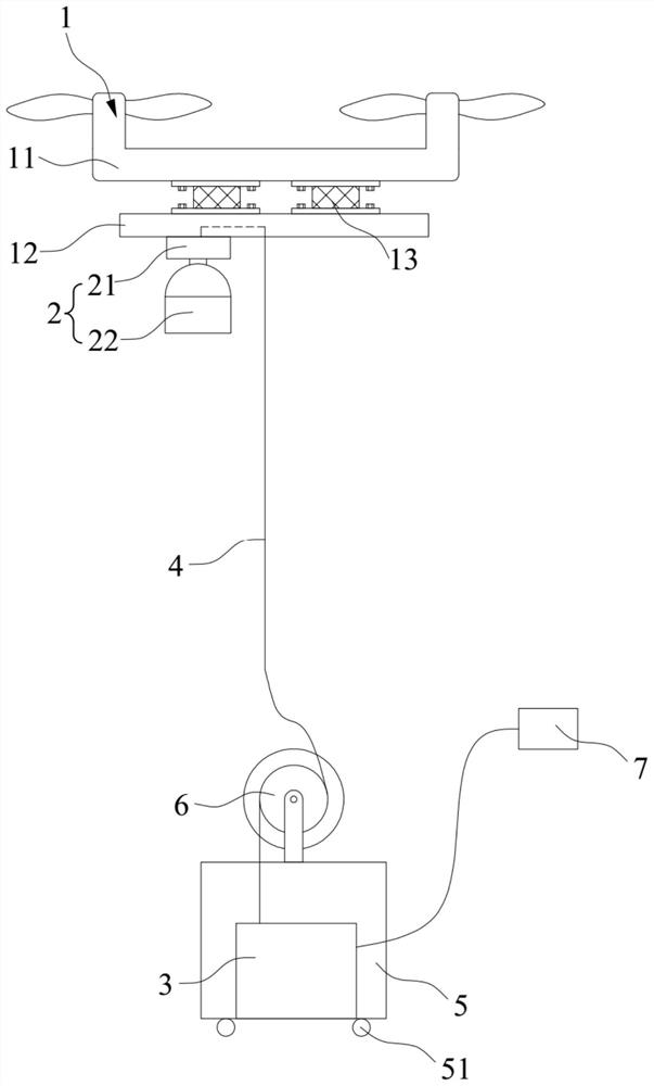
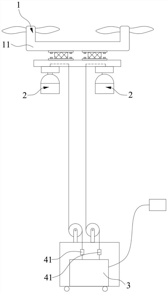
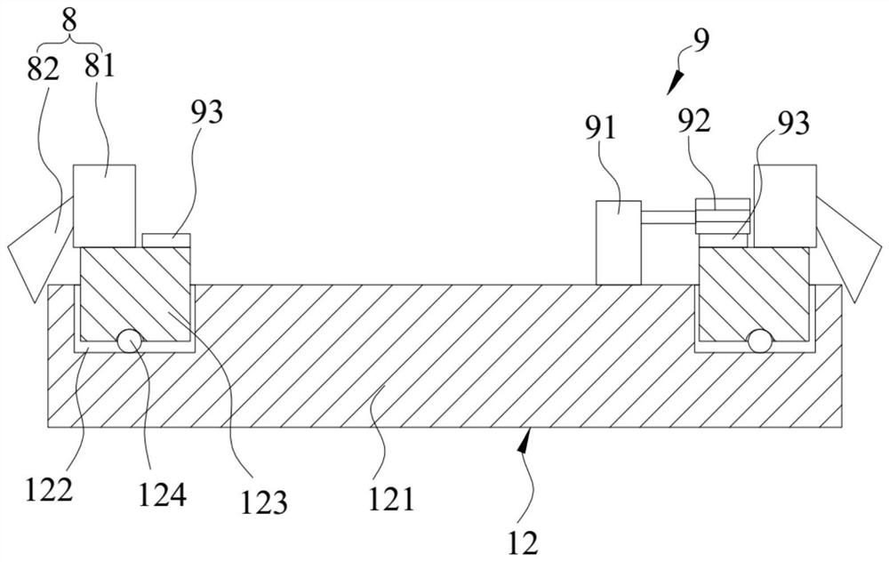
The invention discloses unmanned aerial vehicle lighting equipment, and relates to the technical field of lighting. The unmanned aerial vehicle lighting equipment comprises an unmanned aerial vehicle,a lighting mechanism, a power supply and a cable. The unmanned aerial vehicle comprises a vehicle body, a mounting base and a damping piece, the damping piece is arranged between the vehicle body andthe mounting base, and the mounting base is connected with the bottom of the vehicle body through the damping piece; the lighting mechanism is fixedly connected with the mounting base; the power supply is arranged on the ground; the first end of the cable is electrically connected with the lighting mechanism, and the second end of the same is electrically connected with the power supply. By meansof the damping pieces, shaking of the lighting mechanism can be greatly reduced when the unmanned aerial vehicle flies; meanwhile, by arranging the power supply and the cable, power can be continuously supplied to the lighting mechanism, the power supply burden of a battery of the unmanned aerial vehicle is greatly reduced; therefore, it is guaranteed that the lighting equipment of the unmanned aerial vehicle can provide extremely long lighting time, and workers can conduct long-time continuous operation at night.

Description

technical field [0001] The present invention relates to the technical field of illumination, in particular to an unmanned aerial vehicle illumination device. Background technique [0002] In the process of power grid construction, workers need lighting work when working at high places at night. Because the UAV has the advantages of fixed-point hovering and adjustable flight height, some staff will use the combination of UAV and lighting mechanism for lighting. [0003] However, due to the following two disadvantages of this type of lighting device, the scope of use of this type of lighting device is greatly restricted. One is that UAVs usually vibrate greatly during flight, resulting in serious shaking of the lighting mechanism, which is not conducive to the staff to observe the illuminated objects. Second, because the battery of the UAV must supply the lighting mechanism and the rotor motor at the same time, and the power of the lighting mechanism required for night work ...

Claims


Application Information

Patent Timeline
IPC IPC(8): B64D47/02F16F15/08F21V23/00F21V27/00F21V15/04F21W107/30
CPCB64D47/02F16F15/08F21V15/04F21V23/023F21V27/00F21W2107/30
Inventor 林剑扬邱灿树
Owner GUANGDONG POWER GRID CO LTD
Learn More