Closely-arranged rod bundle fuel assembly thermal hydraulic experiment device

A fuel assembly and thermal-hydraulic technology, applied in the field of thermal-hydraulic experimental devices for closely arranged fuel assemblies

Inactive Publication Date: 2020-09-18
NUCLEAR POWER INSTITUTE OF CHINA
View PDF9 Cites 1 Cited by
  • Summary
  • Abstract
  • Description
  • Claims
  • Application Information

AI Technical Summary

Problems solved by technology

[0004] At present, there are few domestic and foreign patent designs or literatures on the thermal-hydraulic experimental device for closely arranged rod bundle fuel assemblies.

Method used


Image

  • Closely-arranged rod bundle fuel assembly thermal hydraulic experiment device
  • Closely-arranged rod bundle fuel assembly thermal hydraulic experiment device
  • Closely-arranged rod bundle fuel assembly thermal hydraulic experiment device

Examples


Embodiment 1

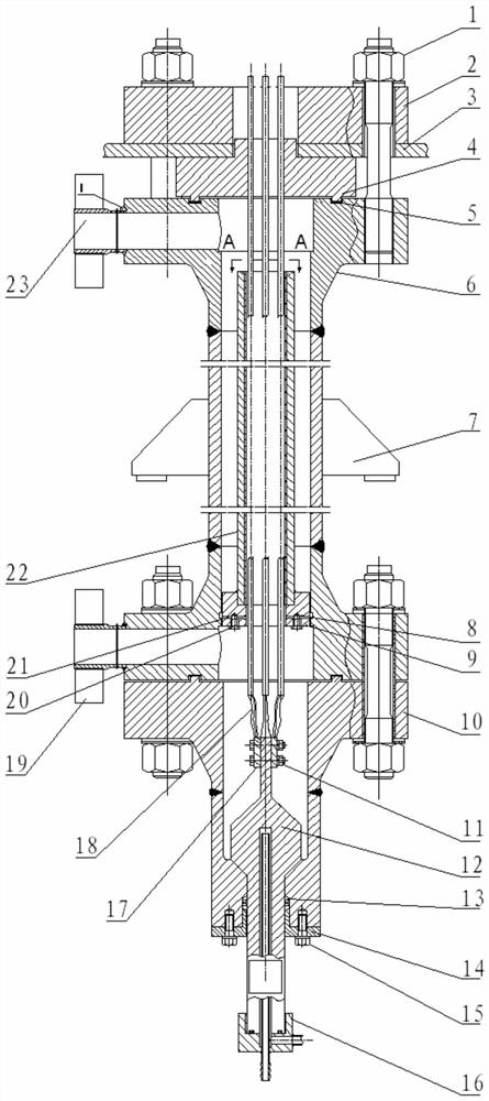
[0051] Such as Figure 1 to Figure 3 As shown, the thermal-hydraulic experimental device for closely arranged rod bundle fuel assemblies includes a pressure-bearing assembly and an electric heating assembly. The pressure-bearing assembly includes a cylinder assembly 6 for providing a pressure boundary, and the electric heating assembly includes a plurality of The element rods of the fuel assembly, the cylinder assembly 6 is also provided with a cold fluid flow channel for providing a fluid boundary, the element rods are arranged at intervals in the cylinder assembly 6, and the element rods are: From one end to the other end, they are copper rod section, stainless steel section and copper rod section;

[0052] On the element rod, the copper rod section at one end is used as the fixed end of the element rod fixed on the pressure-bearing assembly, the copper rod section at the other end is the cantilever end, and the copper rod sections at both ends of the element rod are used as...

Embodiment 2

[0059] The present embodiment is further limited on the basis of embodiment 1, as Figure 1 to Figure 3 As shown, as a more specific implementation form of the electric heating assembly and the fixing method of the element rod, it is set that: the electric heating assembly also includes a conductive head 4 that is insulated and fixedly connected to the cylinder assembly 6, and the conductive head 4 is provided with The number of holes is equal to the number of component rods, and the relative arrangement is consistent with the relative arrangement of component rods;

[0060] The copper rod section at one end of each component rod is embedded in the hole to form an electrical connection and a fixed connection relationship with the conductive head 4;

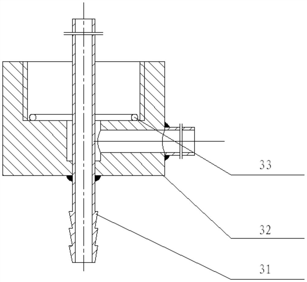
[0061] The electric heating assembly also includes a conductive rod 12 made of copper and fixedly connected to the cylinder assembly 6;

[0062] The conductive head 4 and the conductive rod 12 are located at different ends of the...

Embodiment 3

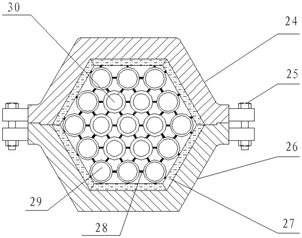
[0075] The present embodiment is further limited on the basis of embodiment 1, as Figure 1 to Figure 3 Shown: As a technical solution for forming the pressure boundary and for forming the boundary of the cold fluid flow channel based on different components to facilitate the design, preparation, installation and versatility of the pressure-bearing components of this experimental device, it is set to: also include fixing The flow channel plate assembly 22 in the barrel assembly 6 is a tubular structure, and the inner space of the flow channel plate assembly 22 serves as part or all of the cold fluid flow channel.

[0076] As a technical solution that facilitates the design of the pressure-bearing component as a tubular container, and the pressure-bearing component has a small structure and high pressure-bearing capacity, and as a technical solution that includes the specific installation form of the flow channel plate component 22, it is set as follows: The axis of the barrel ...


PUM


Abstract

The invention discloses a closely-arranged rod bundle fuel assembly thermal hydraulic experiment device. The device comprises a pressure-bearing assembly and an electric heating assembly, the pressure-bearing assembly comprises a cylinder assembly, the electric heating assembly comprises an element rod, a cold fluid flow channel is further formed in the cylinder assembly, and the element rod comprises a copper rod section, a stainless steel section and a copper rod section from one end to the other end of the element rod. On the element rod, the copper rod section at one end serves as a fixedend of the element rod fixed on the pressure-bearing assembly, the copper rod section at the other end serves as a cantilever end, the cantilever end is electrically connected with the element rod through a flexible wire, the stainless steel sections of the element rods penetrate through the cold fluid flow channel, and the ends of the stainless steel sections are located in the cold fluid flow channel. The thermal hydraulic experiment device has a simple structure, and can accurately simulate a prototype so as to conveniently and accurately carry out thermotechnical hydraulic experimental research on resistance characteristics, critical heat flux density and the like of densely-arranged rod bundle fuel assemblies.

Description

technical field [0001] The invention relates to the technical field of thermal hydraulic test devices, in particular to a thermal hydraulic test device for closely arranged rod bundle fuel assemblies. Background technique [0002] The research on the thermal-hydraulic characteristics of the core fuel assembly is of great significance to the safe operation of the reactor and the design of related systems. In order to improve the performance of the core fuel assembly and optimize its design, all countries have carried out thermal-hydraulic analysis and Experimental research, and proposed a lot of new concepts of heap type. Closely arranged rod bundle fuel assemblies are one of the new fuel assemblies in advanced water-cooled reactors, that is, the fuel elements of the core are arranged closely to form a honeycomb core in which the fuel elements are arranged in triangles and the fuel assemblies are arranged in hexagons. Closely arranging rod bundle fuel assemblies reduces the ...

Claims


Application Information

Patent Timeline
Patent Type & Authority Applications(China)
IPC IPC(8): G21C17/00
CPCG21C17/001Y02E30/30
Inventor 谢峰徐建军黄彦平宫厚军毕景良
Owner NUCLEAR POWER INSTITUTE OF CHINA
Why Eureka
Try Eureka