video camera

A camera and image sensor technology, applied in the field of cameras, can solve problems such as reducing the imaging effect of the camera, and achieve a good imaging effect.

Active Publication Date: 2022-01-07
HANGZHOU HIKVISION DIGITAL TECH
View PDF10 Cites 1 Cited by
  • Summary
  • Abstract
  • Description
  • Claims
  • Application Information

AI Technical Summary

Problems solved by technology

[0004] The existing end plate is fixed on the outer surface of the installation part by an adhesive, and there is a gap between the end plate and the outer surface of the installation part. mouth, and then into the installation cavity of the lens module, reducing the imaging effect of the camera

Method used


Image

  • video camera
  • video camera
  • video camera

Examples


Embodiment 1

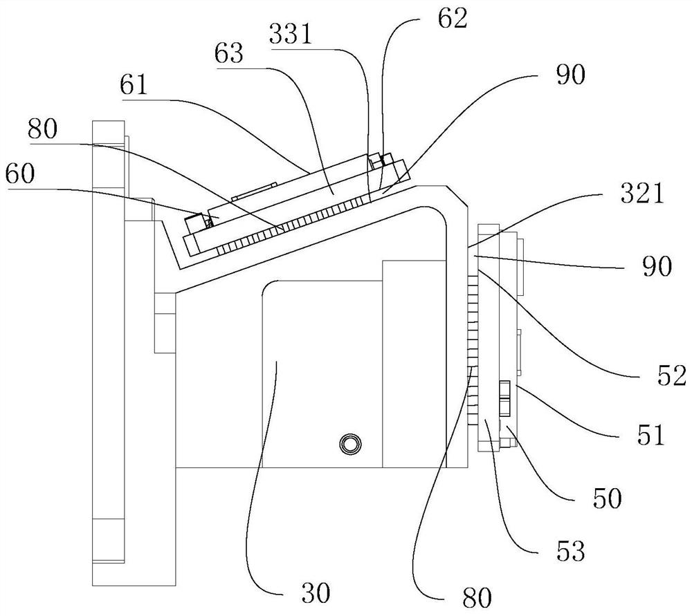
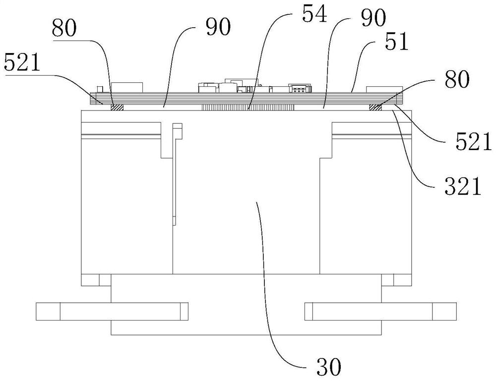
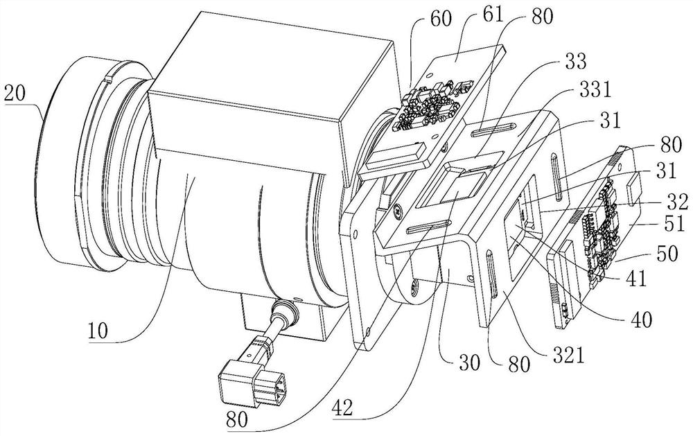
[0031] This embodiment discloses a camera, the camera includes a first housing 10, a lens module and an end plate, the first housing 10 is provided with a window 11, and the first housing 10 has a first installation cavity; the lens module The group is installed in the first installation cavity, the lens module includes a lens 20 , and the lens 20 is arranged opposite to the window 11 . The lens module includes a second housing 30 with a second mounting cavity 31 inside. The second housing 30 has a mounting portion with a light outlet, and the outer surface of the mounting portion is the mounting surface. An image sensor is arranged on the end plate, the image sensor is set opposite to the light outlet, the end plate is connected to the installation part, and a sealing body 70 is arranged between the end plate and the installation surface, and the sealing body 70 is arranged around the periphery of the light outlet.

[0032] There is a gap between the end plate of the existing...


PUM


Abstract

The invention relates to a video camera, which comprises a first housing, a lens module and an end plate. The first housing is provided with a viewing window and has a first installation cavity inside the first housing. The lens module is installed in the first installation cavity, the lens module includes a lens, and the lens is arranged opposite to the window. The lens module includes a second housing, which has a second installation cavity, the second housing has a mounting portion, a light outlet is arranged on the mounting portion, and the outer surface of the mounting portion is a mounting surface. An image sensor is arranged on the end plate, the image sensor is set opposite to the light outlet, the end plate is connected to the installation part, and a sealing body is arranged between the end plate and the installation surface, and the sealing body is arranged around the light outlet. A sealing body is arranged between the end plate and the mounting surface, and the sealing body isolates the light outlet from the outside world, thereby preventing external dust and light from entering the second installation cavity from the light outlet, and preventing the external dust and light from affecting the imaging of the camera. The imaging effect of the video camera of the present invention is better.

Description

technical field [0001] The invention relates to a video camera. Background technique [0002] The video camera includes a casing with an installation cavity inside, and a window is opened on the casing, and a transparent protective cover is generally installed on the window. A lens module is installed in the installation cavity, the lens module includes a lens, and the lens is arranged opposite to the protective cover. [0003] The lens module includes a housing with an installation cavity inside the lens module. Optical elements are arranged in the installation cavity of the lens module, and the optical elements can process and transmit optical signals. The casing has a mounting portion, and a light outlet is opened on the mounting portion. The image sensor is arranged on the end plate, the end plate is connected with the installation part, the image sensor is arranged opposite to the light outlet, and the image sensor is arranged opposite to the optical element. The ima...

Claims


Application Information

Patent Timeline
Patent Type & Authority Patents(China)
IPC IPC(8): H04N5/225G03B17/02
CPCG03B17/00G03B2217/002H04N23/45H04N23/55H04N23/51H04N23/54
Inventor 李杨叶展
Owner HANGZHOU HIKVISION DIGITAL TECH
Why Eureka
Try Eureka