A multi-degree-of-freedom sample holder

A sample rod and degree of freedom technology, applied in the field of sample rods, can solve the problems of easy deformation of flexible claws, inability to grasp small balls, deviation, etc., and achieve the effect of reducing design and manufacturing requirements

Active Publication Date: 2021-03-05
ZHEJIANG UNIV
View PDF15 Cites 0 Cited by
  • Summary
  • Abstract
  • Description
  • Claims
  • Application Information

AI Technical Summary

Problems solved by technology

[0005] The disadvantages of this three-dimensional probe are: 1. The flexible claw is easy to deform. In order to maintain the friction between it and the ball, the shape of the flexible claw needs to be adjusted frequently, but there are many flexible claws, and it is impossible to ensure that each The consistency of the flexible wire claws, resulting in the lower and lower reliability and accuracy of the three-dimensional probe with the time and frequency of use
2. The length of the flexible wire claw makes there is a gap between the sample holder and the ball. When the ball circulates, the sample holder will move away from the ball or close to the ball along the wire claw, so as to realize the axial displacement of the sample. , but the sample holder is suspended on the ball through flexible wire claws, the sample holder and the sample on it will fall down due to gravity, and the position accuracy is not high
The observation field of view in the transmission electron microscope is at the nanometer and micron level, and the position deviation of the sample due to gravity is likely to cause the area to be observed on the sample to deviate from the observation field of view of the electron microscope and cannot be observed; and the existence of position deviation makes it difficult to place the sample Adjust the area to be observed to a suitable position and angle for observation
3. When the probe clamping device moves back and forth along the axial direction of the piezoelectric ceramic tube, the relationship between the shape of the flexible wire claw and the above-mentioned frictional force is complicated, and it is difficult to ensure that the frictional force is always suitable by adjusting its shape
In addition, the probe clamping device is affected by gravity, which makes it easy to generate coupling motion during rough adjustment, and it is difficult to accurately control the probe; even due to improper adjustment of the shape of the flexible wire claw, the small ball cannot be grasped, which may cause the probe to clamp The device falls into the device, causing damage to the device

Method used


Image

  • A multi-degree-of-freedom sample holder
  • A multi-degree-of-freedom sample holder
  • A multi-degree-of-freedom sample holder

Examples


Embodiment Construction

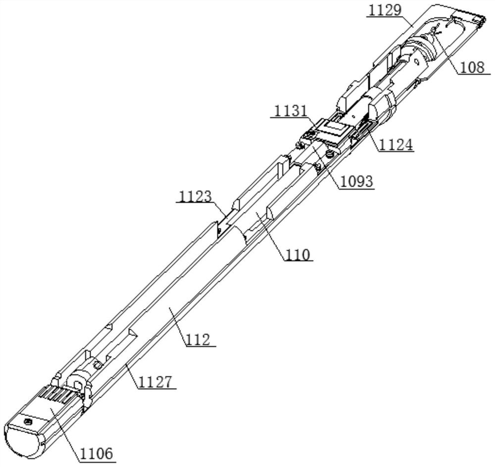
[0166] figure 1 For a multi-freedom sample rod. Such as figure 2 As shown, a nanopatchizer is provided on the sample lever, and the nanopatchizer includes a drive member 101, a joint ball 103, and a press member, and the joint ball 103 is fixed, and the press assembly includes at least two press 105 and an elastic connection. The component 104, the elastic connection assembly 104 connects adjacent pressures, and the press fittings holds the joint ball 103, and the press and the joint ball 103 have a preload. For example, a piezoelectric ceramic tube as a drive member 101.

[0167] Press

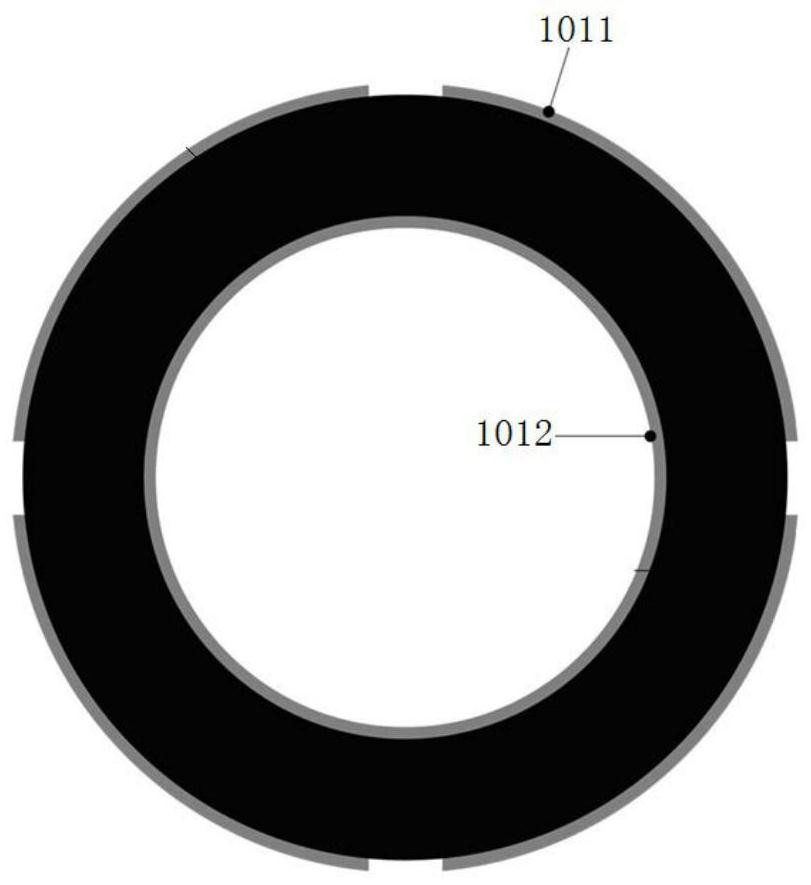
[0168] In some embodiments, if figure 2 As shown, each of the pressures has a recess 1051 and a connecting portion 1052, and the elastic connection assembly 104 is disposed between the connecting portion 1052 of the adjacent pressure, and the recess 1051 of all press is composed of the joint ball 103. . The dimples are in contact with the joint ball 103 wire contact or point contact; the elas...


PUM


Abstract

The invention discloses a multi-degree-of-freedom sample rod, which comprises a shell and a rotating shaft. A skeleton is arranged between the shell and the rotating shaft, and the skeleton is coaxial with the shell and the rotating shaft. When assembling, make the rotating shaft and frame coaxial, and then put the rotating shaft-skeleton into the shell, so that the rotating shaft, frame and shell are coaxial, and the installation accuracy is improved; in addition, the frame also provides the installation position for the rotating shaft drive assembly, and the frame also plays a role The function of separating the shaft from the wire and preventing the wire from interfering with the movement of the shaft.

Description

Technical field [0001] The present invention relates to an electron microscope, a sample rod used under transmissive electron microscope. Background technique [0002] Transmission Electron Microscope (TEM) can be seen in a normal optical microscope that is less than 0.2 μm mini structure, which is called sub-microstructure or ultrastructure. In 1932, RUSKA invented a transmission electron microscope with an electron beam as a light source, and the current TEM resolution can reach 0.2 nm. [0003] In situ observation technology has a long history in the study of transmission electron microscope. By applying a variety of physical effects on the sample, the microstructure and chemical state of the material are observed by transmitting electron microscopy (transmission electron microscopy), and the performance performance of the material or device in the actual use process can be visually studied. Studies have important practical significance. The in situ technology in the transmiss...

Claims


Application Information

Patent Timeline
Patent Type & Authority Patents(China)
IPC IPC(8): G01N23/02G01N23/20025H01J37/20
CPCG01N23/04G01N2223/03G01N2223/102H01J37/20H01J2237/2007
Inventor 王宏涛张奕志
Owner ZHEJIANG UNIV
Why Eureka
Try Eureka