Unattended oil field transfer station robot based on image recognition system

An image recognition and robot technology, applied in the field of robotics, can solve the problems of easily affecting camera imaging, accumulating dust, inconvenient camera shading, etc., to achieve the effects of convenient use, easy shading, and simple structure

Inactive Publication Date: 2021-12-31
深圳市中科智清新能源科技有限公司
View PDF0 Cites 0 Cited by
  • Summary
  • Abstract
  • Description
  • Claims
  • Application Information

AI Technical Summary

Problems solved by technology

[0004] The purpose of the present invention is to solve the problems in the prior art that the unattended oil field conversion station robot is not convenient to clean the camera during use, which leads to the accumulation of dust after long-term use, which reduces the definition of the camera, and during use In the process, it is not convenient to shade the camera, which leads to the disadvantage that strong light can easily affect the imaging of the camera, and an unattended oilfield switching station robot based on an image recognition system is proposed

Method used


Image

  • Unattended oil field transfer station robot based on image recognition system
  • Unattended oil field transfer station robot based on image recognition system
  • Unattended oil field transfer station robot based on image recognition system

Examples


Embodiment 1

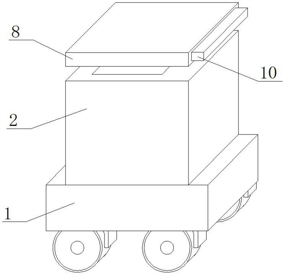
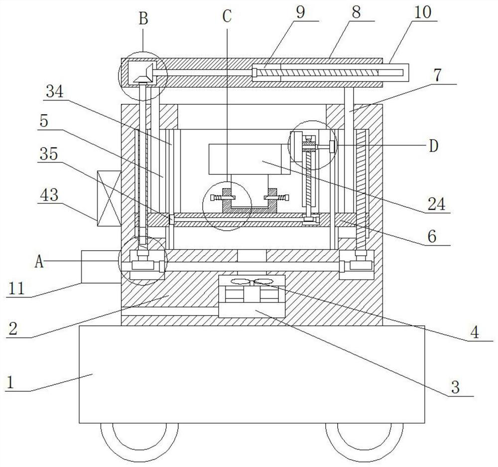
[0029] refer to Figure 1-7 , an unattended oil field switching station robot based on an image recognition system, comprising a robot main body 1, a storage box 2 is installed on the top of the robot main body 1 through bolts, and a first installation slot 3 is opened in the storage box 2, and the first installation A heat dissipation fan 4 is fixedly installed in the groove 3 by bolts, and the inner walls of both sides of the storage box 2 are provided with a first chute 5, and the same mounting plate 6 is slidably installed in the two first chute 5, and the top of the mounting plate 6 Mounting seat 22 is fixedly installed by welding, and the top of mounting seat 22 is provided with the 3rd chute, and connecting post 23 is slidably installed in the 3rd chute, and the top of connecting post 23 is fixed with camera 24 by bolt, on the mounting plate 6 A lifting mechanism is provided, and the top inner walls of the two first slide grooves 5 are provided with first sliding holes,...

Embodiment 2

[0039] The difference with Embodiment 1 is that the outside of the motor 11 is fixedly connected to one side of the storage box 2, two symmetrical first empty slots 12 are opened in the storage box 2, and a first Through hole, the first through hole communicates with the two first empty slots 12, the first worm 13 is installed in rotation in the first through hole, one end of the first worm 13 is fixedly connected with the output shaft of the motor 11 by welding, the two second The bottom inner wall of a chute 5 is provided with a second through hole, and the two second through holes communicate with the two first empty slots 12 respectively, and the mounting plate 6 is provided with two symmetrical first threaded holes, and the two second through holes communicate with each other respectively. A first threaded mandrel 14 is installed in a threaded hole, and one end of the two first threaded mandrels 14 is fixedly installed with a first worm wheel 15 by welding, and the two fir...


PUM


Abstract

The invention belongs to the field of robots, and particularly relates to an unattended oil field transfer station robot based on an image recognition system. According to an existing unattended oil field transfer station robot, a camera is inconvenient to clean in the use process, dust is accumulated after long-time use, and the definition of the camera is reduced; and in the use process, the camera is inconvenient to shade, so that the strong light is easy to influence the imaging of the camera. In order to solve said problems, the following scheme is provided: the robot comprises a robot body; a storage box is fixedly mounted at the top of the robot body through bolts, and a first mounting groove is formed in the storage box. According to the invention, the camera can be cleaned conveniently in the use process, so that the definition of the camera can be prevented from being reduced by dust; the camera can be conveniently shaded in the use process, so that the influence of strong light on imaging of the camera is avoided; the structure is simple and use is convenient.

Description

technical field [0001] The invention relates to the technical field of robots, in particular to an unattended oilfield switching station robot based on an image recognition system. Background technique [0002] Image recognition technology is an important field of artificial intelligence. It refers to the technology of object recognition on images to identify targets and objects in various patterns. With the expansion of oilfield development scale, the contradiction between the increasing demand for oilfield production labor and the natural decline of in-service employees has become increasingly prominent. The digital construction of oil and gas production is an effective way to promote the optimization of production organization model, improve the utilization rate of human resources, and solve the production labor demand. The intelligent inspection robot has image recognition, infrared thermal imaging, voice recognition, gas state detection and other functions, and can rea...

Claims


Application Information

Patent Timeline
Patent Type & Authority Applications(China)
IPC IPC(8): H04N5/225B25J11/00
CPCB25J11/00H04N23/52H04N23/51
Inventor 章斌
Owner 深圳市中科智清新能源科技有限公司
Why Eureka
Try Eureka