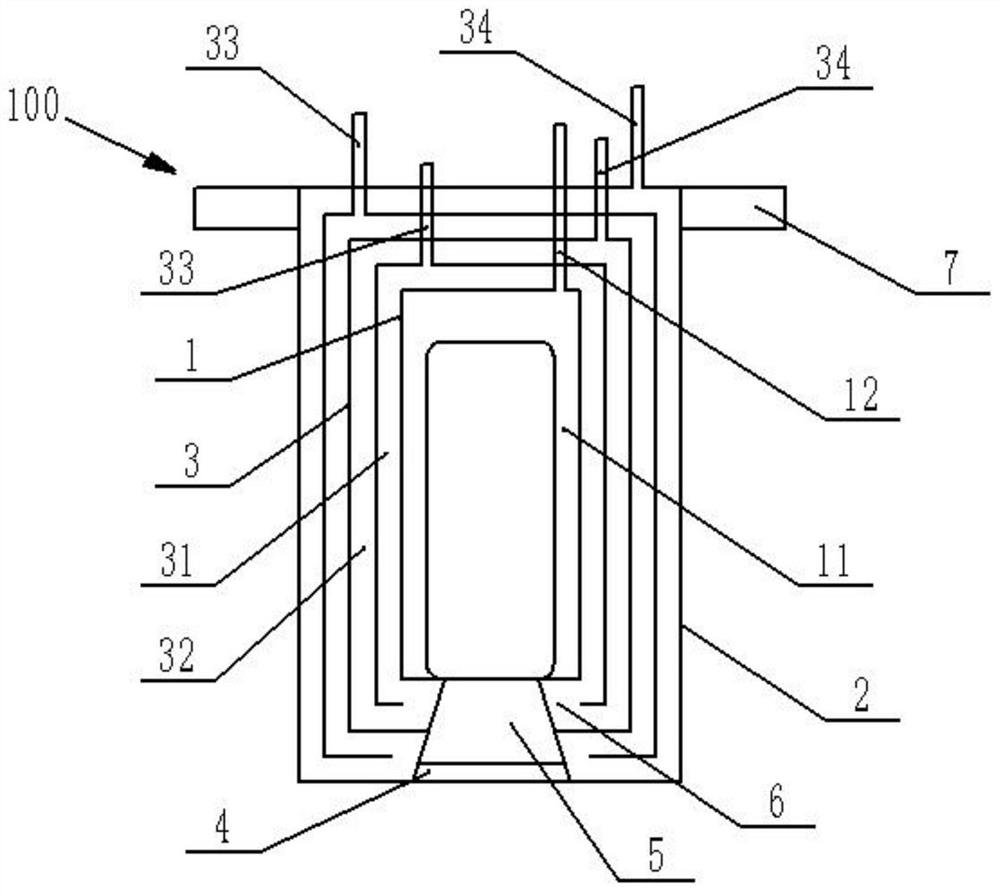
Monitoring equipment in high-temperature furnace

A technology for monitoring equipment and high-temperature furnaces, applied in the field of monitoring equipment in high-temperature furnaces, can solve problems such as unfavorable energy saving and emission reduction, insufficient combustion, poor cooling effect, etc., and achieve the advantages of avoiding dust affecting imaging, good cooling effect, and wide application range Effect

Inactive Publication Date: 2021-11-05
CHANGSHA UNIVERSITY
View PDF2 Cites 0 Cited by
  • Summary
  • Abstract
  • Description
  • Claims
  • Application Information

AI Technical Summary

Problems solved by technology

For example, a water-cooled air-sealed high-temperature industrial TV system disclosed by the patent authorization number CN201429337Y and a high-temperature industrial TV device in a blast furnace disclosed by the patent authorization number CN100529107C. The casing air cooling method cools the camera device, and the cooling effect is poor. At the same time, the cold gas in the two schemes is discharged into the furnace through the camera, resulting in a decrease in the temperature inside the furnace and insufficient combustion, which will increase the NO X Emissions are not conducive to energy saving and emission reduction. The introduction of cold air into the furnace during oxy-fuel combustion will cause changes in gas components and affect production. There are restrictions on the use of both devices in the furnace during oxy-fuel combustion. In addition, the blast furnace furnace High-temperature industrial TV devices also have the problem that dust inside the furnace will enter the casing and interfere with the monitoring effect

Method used


Image

  • Monitoring equipment in high-temperature furnace

Examples


Embodiment Construction

[0020] The following will clearly and completely describe the technical solutions in the embodiments of the present invention with reference to the accompanying drawings in the embodiments of the present invention. Obviously, the described embodiments are only some, not all, embodiments of the present invention. Based on the embodiments of the present invention, all other embodiments obtained by persons of ordinary skill in the art without making creative efforts belong to the protection scope of the present invention.

[0021] The object of the present invention is to provide a monitoring device in a high-temperature furnace to solve the problems existing in the prior art, which can prevent dust from affecting imaging, has a good cooling effect, and has a wide range of applications.

[0022] In order to make the above objects, features and advantages of the present invention more comprehensible, the present invention will be further described in detail below in conjunction wit...


PUM


Abstract

The invention discloses monitoring equipment in a high-temperature furnace, and relates to the technical field of high-temperature monitoring equipment. The monitoring equipment comprises an inner-layer cavity, a shell and a high-temperature-resistant observation window, and a camera device is fixedly arranged in the inner-layer cavity; the shell is arranged outside the inner-layer cavity in a sleeving manner, at least one cooling layer is arranged between the inner-layer cavity and the shell, the cooling layer comprises an inner cooling chamber and an outer cooling chamber, the outer cooling chamber is arranged outside the inner cooling chamber in a sleeving manner, the inner cooling chamber is communicated with the outer cooling chamber, the inner cooling chamber is provided with a cooling medium inlet, and the outer cooling chamber is provided with a cooling medium outlet; the cooling medium inlet and the cooling medium outlet are both communicated with the outside of a hearth; and the high-temperature-resistant observation window is arranged on the shell in a sealed manner, and the camera device can monitor the combustion condition in the hearth through the high-temperature-resistant observation window. The monitoring equipment in the high-temperature furnace can prevent dust from affecting imaging, and is good in cooling effect and wide in application range.

Description

technical field [0001] The invention relates to the technical field of high-temperature monitoring equipment, in particular to a monitoring equipment in a high-temperature furnace. Background technique [0002] In the prior art, there is a high-temperature monitoring device for furnaces that uses camera equipment to be installed inside the hearths of high-temperature furnaces, industrial furnaces for melting furnaces, etc., to monitor the melting of minerals and the working state of the furnace wall. For example, a water-cooled air-sealed high-temperature industrial TV system disclosed by the patent authorization number CN201429337Y and a high-temperature industrial TV device in a blast furnace disclosed by the patent authorization number CN100529107C. The casing air cooling method cools the camera device, and the cooling effect is poor. At the same time, the cold gas in the two schemes is discharged into the furnace through the camera, resulting in a decrease in the tempera...

Claims


Application Information

Patent Timeline
Patent Type & Authority Applications(China)
IPC IPC(8): F27D21/02F27D9/00
CPCF27D21/02F27D9/00F27D2021/026F27D2009/0002
Inventor 李勇刘沛林杨佳念王春黄格童光展
Owner CHANGSHA UNIVERSITY
Why Eureka
Try Eureka