
A self-cleaning smart home fingerprint lock

A smart home and self-cleaning technology, applied in cleaning equipment, household cleaning devices, building locks, etc., can solve problems such as indirect cross-infection and fingerprint imprint safety hazards, and achieve the effect of improving cleanliness

Active Publication Date: 2021-06-04
常州市大华锁厂有限公司
View PDF8 Cites 0 Cited by
  • Summary
  • Abstract
  • Description
  • Claims
  • Application Information

AI Technical Summary

Problems solved by technology

[0005] The purpose of the present invention is to solve the shortcomings of the existing fingerprint locks in the prior art, such as the potential safety hazards and the risk of indirect cross-infection of the fingerprint imprint on the LCD screen, and propose a self-cleaning smart lock. Home fingerprint lock

Method used


Image

  • A self-cleaning smart home fingerprint lock
  • A self-cleaning smart home fingerprint lock

Examples


Embodiment 1

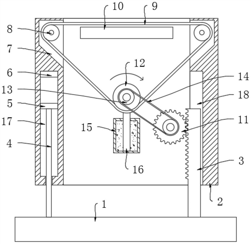
[0020] refer to figure 1 , a self-cleaning smart home fingerprint lock, including a base 1, a movable shell 2 is connected to the base 1 through a limit mechanism, and the upper end of the inner wall of the movable shell 2 is symmetrically provided with installation grooves 7, and each installation groove 7 is rotated A driven roller 8 is installed, and a drive roller 12 is mounted on the inner wall of the movable shell 2 to rotate, and a transparent film 9 is set on the drive roller 12 and a plurality of driven rollers 8, and a liquid crystal screen 10 is fixedly arranged on the upper side of the movable shell 2 inner wall, When the user presses on the liquid crystal screen 10 through the transparent film 9, the verification module in the liquid crystal screen 10 can quickly carry out retrieval verification for identification (this technology is a prior art, and will not be described in detail here), and the liquid crystal screen 10 The extension surface of the upper end surf...

Embodiment 2

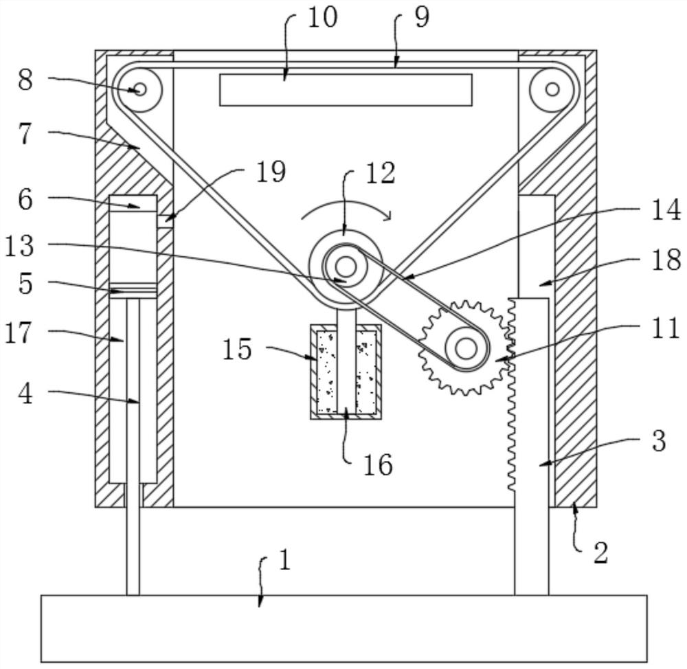
[0026] refer to figure 2 The difference between this embodiment and Embodiment 1 is that the side wall of each first permanent magnet block 5 is sealed and slidably connected with the groove wall of the corresponding limiting groove 17 through a sealing ring, and the upper end of the groove wall of the limiting groove 17 is opened There is a through hole 19 communicating with the inside of the movable shell 2 , and the through hole 19 is opposite to the outer side wall of the transparent membrane 9 .

[0027] When the present embodiment is in use, when the movable shell 2 moves downward, the gas between the first permanent magnet block 5 and the second permanent magnet block 6 is extruded through the through hole 19 and discharged into the movable shell 2 and blows to the absorbed water. The transparent film 9 part after strip 16 cleaning can accelerate the air-drying speed of the disinfectant on the transparent film 9, and when avoiding the frequent use of the fingerprint lo...


PUM


Abstract

The invention discloses a self-cleaning smart home fingerprint lock, which comprises a base, a movable shell is connected to the base through a limit mechanism, and the upper end of the inner wall of the movable shell is symmetrically opened with installation grooves, each of the installation grooves Driven rollers are rotatably installed inside, and driving rollers are rotatably installed on the inner wall of the movable shell. A transparent film is set on the driving roller and a plurality of driven rollers, and a liquid crystal screen is fixed on the upper side of the inner wall of the movable shell. , the inner wall of the movable shell is provided with a chute, the base is vertically fixedly connected with a rack, and the rack is slidably connected with the chute. In the present invention, each time the user uses the liquid crystal screen to verify the fingerprint, the outer surface of the transparent film can be automatically cleaned to eliminate fingerprints and disinfected, which can prevent criminals from stealing fingerprints and can protect the transparent film. Carry out disinfection treatment to improve the cleanliness of the fingerprint lock and avoid cross contact between users who have used the fingerprint lock successively.

Description

technical field [0001] The invention relates to the technical field of intelligent security equipment, in particular to a self-cleaning intelligent household fingerprint lock. Background technique [0002] Compared with ordinary key-type door locks, using fingerprint locks, users do not need to carry keys, which greatly reduces the travel burden of users. Especially in summer, people's clothes are loose and it is inconvenient to carry keys. It avoids the embarrassing phenomenon of being unable to open the door due to the loss of the key, and the current fingerprint lock has the characteristics of convenience, speed, and accuracy, and has the character of technological furniture. Therefore, fingerprint locks are becoming more and more sought after and welcomed by people in the smart home market. [0003] However, there are also some problems in the actual use of the fingerprint lock. For example, when the user presses the LCD screen to verify the fingerprint, the user's finge...

Claims


Application Information

Patent Timeline
Patent Type & Authority Patents(China)
IPC IPC(8): E05B17/00A61L2/18A47L25/00G07C9/00
CPCA47L25/00A61L2/18E05B17/00G07C9/00563
Inventor 杨作莲
Owner 常州市大华锁厂有限公司
Learn More