Multifunctional diaphragm and biological microporous plate microimaging light path device
A microscopic imaging and multi-functional technology, applied in the optical field, can solve problems such as unfavorable accuracy, and achieve the effect of compact structure, improved optical path, and uniform light.
- Summary
- Abstract
- Description
- Claims
- Application Information
AI Technical Summary
Problems solved by technology
Method used
Image

Examples
Embodiment 1
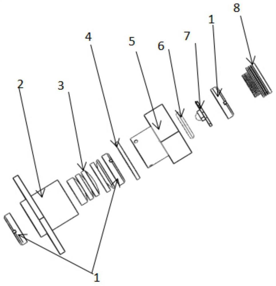
[0053] This embodiment provides an optical path device for microscopic imaging of a biological microplate, and the structural schematic diagram of the optical path device for microscopic imaging of a biological microplate is as follows figure 1 As shown, it includes three sequentially arranged light source components, diaphragm components and imaging lens groups; the central axis of the light source component, the central axis of the three imaging lens groups and the central axis of the multifunctional diaphragm 4 coincide.
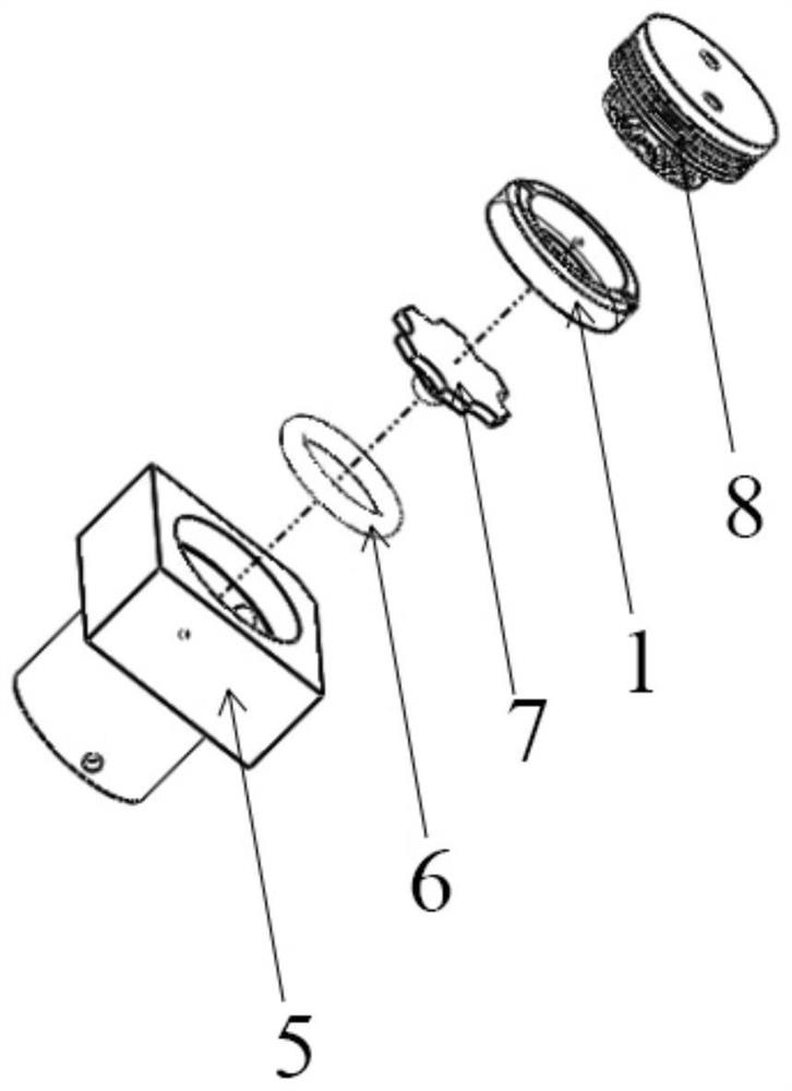
[0054] The structural schematic diagram of the light source assembly is as follows figure 2 As shown, it includes a light source seat 5, a sealing ring 6, an LED light source 7, a fixing part 1 and a heat sink 8, and the central axes of the light source seat 5, the sealing ring 6, the LED light source 7, the fixing part 1 and the heat sink 8 coincide; The sealing ring 6 and the fixing member 1 are used to fix the LED light source 7 to the light source se...
Embodiment 2
[0060] This embodiment provides an optical path device for microscopic imaging of a biological microplate, and the structural schematic diagram of the optical path device for microscopic imaging of a biological microplate is as follows figure 1 As shown, it includes three sequentially arranged light source components, diaphragm components and imaging lens groups; the central axis of the light source component, the central axis of the three imaging lens groups and the central axis of the multifunctional diaphragm 4 coincide.
[0061] The structural schematic diagram of the light source assembly is as follows figure 2 As shown, it includes a light source seat 5, a sealing ring 6, an LED light source 7, a fixing part 1 and a heat sink 8, and the central axes of the light source seat 5, the sealing ring 6, the LED light source 7, the fixing part 1 and the heat sink 8 coincide; The sealing ring 6 and the fixing member 1 are used to fix the LED light source 7 to the light source se...
Embodiment 3
[0068] This embodiment provides an optical path device for microscopic imaging of a biological microplate, and the structural schematic diagram of the optical path device for microscopic imaging of a biological microplate is as follows figure 1 As shown, it includes three sequentially arranged light source components, diaphragm components and imaging lens groups; the central axis of the light source component, the central axis of the three imaging lens groups and the central axis of the multifunctional diaphragm 4 coincide.
[0069] The structural schematic diagram of the light source assembly is as follows figure 2 As shown, it includes a light source seat 5, a sealing ring 6, an LED light source 7, a fixing part 1 and a heat sink 8, and the central axes of the light source seat 5, the sealing ring 6, the LED light source 7, the fixing part 1 and the heat sink 8 coincide; The sealing ring 6 and the fixing member 1 are used to fix the LED light source 7 to the light source se...
PUM
 Abstract
Description
Claims
Application Information
 - R&D Engineer
- R&D Manager
- IP Professional
- Industry Leading Data Capabilities
- Powerful AI technology
- Patent DNA Extraction
Browse by: Latest US Patents, China's latest patents, Technical Efficacy Thesaurus, Application Domain, Technology Topic.
© 2024 PatSnap. All rights reserved.Legal|Privacy policy|Modern Slavery Act Transparency Statement|Sitemap