
Intelligent access control device

A technology of intelligent access control and assembly mechanism, which is applied in the field of access control, and can solve problems such as inconvenient disassembly and assembly of end covers, inconvenient replacement of baffles, and damage to cameras

Pending Publication Date: 2020-09-25
山东平祥智能科技有限公司
View PDF0 Cites 2 Cited by
  • Summary
  • Abstract
  • Description
  • Claims
  • Application Information

AI Technical Summary

Problems solved by technology

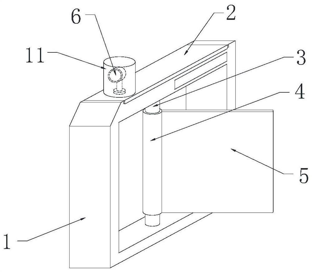
[0003] The currently used access control devices have certain defects. The lack of a convenient installation and replacement mechanism for the baffle makes it inconvenient to replace the baffle when it is damaged, which reduces the practicability of the access control device. At the same time, the lack of a protection mechanism makes it inconvenient to protect the camera and easily causes The damage of the camera and the lack of assembly mechanism at the same time make it inconvenient to disassemble and assemble the end cover, and then partially maintain the parts inside the frame

Method used


Image

  • Intelligent access control device
  • Intelligent access control device
  • Intelligent access control device

Examples


Embodiment Construction

[0031] In order to make the purpose, features and advantages of the present application more obvious and understandable, the technical solutions in the embodiments of the present application will be clearly and completely described below in conjunction with the drawings in the embodiments of the present application. Obviously, the following The described embodiments are only some of the embodiments of the present application, but not all of them. Based on the embodiments in this application, all other embodiments obtained by persons of ordinary skill in the art without making creative efforts belong to the scope of protection of this application.

[0032] The technical solution of the present application will be further described below in conjunction with the accompanying drawings and through specific implementation methods.

[0033] In the description of the present application, it should be understood that the orientation or positional relationship indicated by the terms "up...


PUM


Abstract

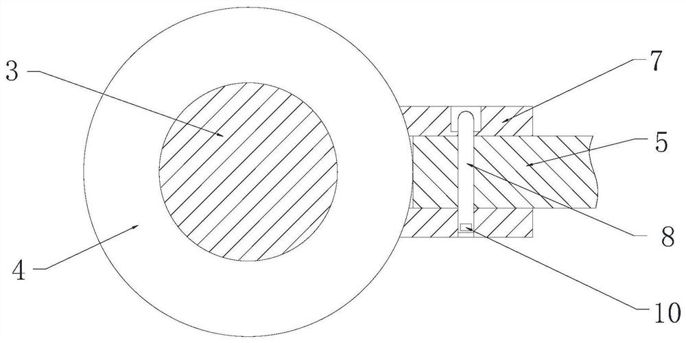
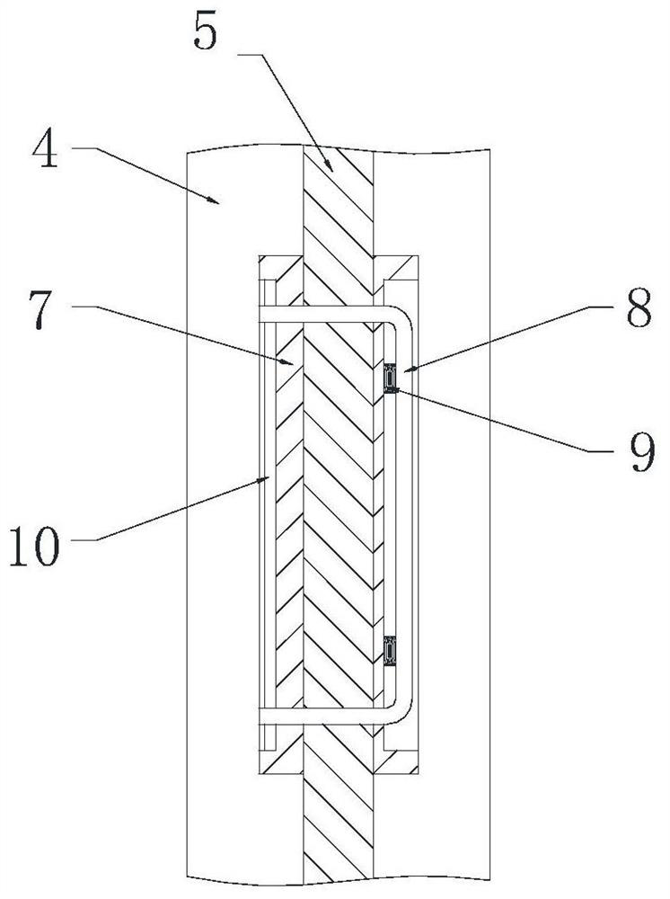
The application discloses an intelligent access control device. The device comprises a frame, an end cover, a rotating shaft, a cylinder, a baffle, a camera, fixing pieces, a U-shaped rod, a first spring, a clamping rod, a transparent protection cylinder, an annular groove, clamping grooves, T-shaped blocks, a pressing plate, a first ball, square rods, a circular groove, L-shaped grooves, T-shapedrods, sliding blocks, a third spring and a transparent protection sleeve. The T-shaped blocks are driven to move through rectangular grooves formed in the clamping grooves, so that the T-shaped blocks extend to the lower side of the end cover, then the transparent protective sleeve is rotated, the transparent protective sleeve rotates to drive the T-shaped blocks to move into arc grooves; and thetransparent protective sleeve pulls the T-shaped blocks upwards under the action of the elastic force of the second spring, so that the T-shaped blocks are attached to the bottom end of the end coverto form a circular ring. According to the device, the T-shaped rods move to drive the sliding blocks to move into vertical grooves of the L-shaped grooves; and when the sliding blocks move to the ends of the vertical grooves, a user rotates the T-shaped rods, and the T-shaped rods rotate to drive the sliding blocks to move into the transverse groove.

Description

technical field [0001] The application relates to an access control device, specifically an intelligent access control device, which belongs to the technical field of access control. Background technique [0002] Refers to the prohibition authority of the door, which is the guard against the door. The door here, in a broad sense, includes various passages that can pass, including doors for people, doors for vehicles, etc. Therefore, access control includes vehicle access control. In the application of parking lot management, vehicle access control is an important means of vehicle management. [0003] The currently used access control devices have certain defects. The lack of a convenient installation and replacement mechanism for the baffle makes it inconvenient to replace the baffle when it is damaged, which reduces the practicability of the access control device. At the same time, the lack of a protection mechanism makes it inconvenient to protect the camera and easily c...

Claims


Application Information

Patent Timeline
IPC IPC(8): G07C9/10
CPCG07C9/10
Inventor 姚新水姚汶君
Owner 山东平祥智能科技有限公司
Learn More