
Steel strand bending device and using method thereof

A technology of steel strands and benders, applied in the field of power tools, can solve problems such as time-consuming and laborious, and achieve the effects of improving process quality, strong applicability, and simple and fast bending

Inactive Publication Date: 2020-09-29
GUANGDONG POWER GRID CO LTD +1
View PDF6 Cites 2 Cited by
  • Summary
  • Abstract
  • Description
  • Claims
  • Application Information

AI Technical Summary

Problems solved by technology

[0003] The purpose of the present invention is to provide a steel strand bender to solve the time-consuming and labor-intensive technical problem of manually bending steel strands in the prior art, realize standardized, fast and labor-saving bending of steel strands, and improve process quality and efficiency

Method used


Image

  • Steel strand bending device and using method thereof
  • Steel strand bending device and using method thereof

Examples


Embodiment 1

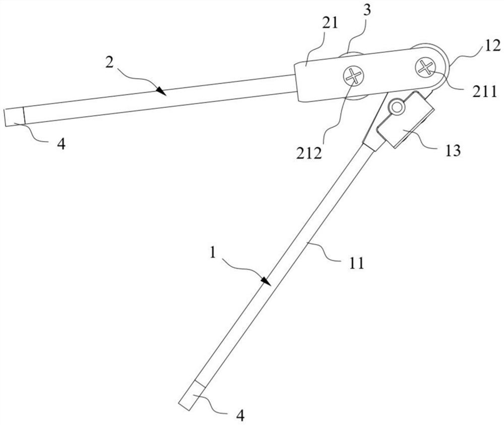
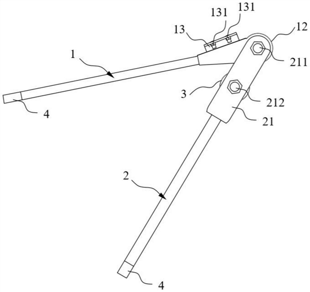
[0035] This embodiment provides a steel strand bender, such as figure 1 and figure 2 As shown, it includes a rod body 11 , an arc-shaped end 12 and a rotating handle 2 . There are multiple arc-shaped ends 12, and the radii of the outer edges of the plurality of arc-shaped ends 12 increase sequentially. One end of the rod body 11 can be selectively connected to an arc-shaped end 12 to form a fixed handle 1. One side of the arc-shaped end 12 is provided with Fixed part 13, fixed part 13 is used for fixing one end of the steel strand; One end of the rotating handle 2 is the working end, and the working end is connected with the arc-shaped end 12 of the fixed handle 1 in rotation. One end of the stranded wire is fixed by the fixing part 13, and when the other end goes around the arc-shaped end 12 and passes through the wire passing hole, the rotating handle 2 can rotate toward the fixed handle 1 to bend the steel stranded wire. Among them, the steel strand bender has a pluralit...

Embodiment 2

[0047] This embodiment provides a method for using the steel strand bender provided in the first embodiment, wherein the same or corresponding components as those in the first embodiment are designated with reference numerals corresponding to those in the first embodiment. For simplicity, only the differences between Embodiment 2 and Embodiment 1 are described. The difference is that the method for using the steel strand bender provided in Embodiment 1 includes the following steps:

[0048] S1. According to the working conditions, select the arc-shaped end 12 with the required outer edge radius and connect it with the rod body 11, and then connect it with the rotating handle 2;

[0049] S2. Rotate the rotating handle 2 and the fixed handle 1 to form a preset angle;

[0050] S3. Fix one end of the steel strand to the fixed handle 1 through the fixing part 13, and the other end passes through the arc-shaped end 12 and passes through the wire through hole;

[0051] S4. The free...


PUM


Abstract

The invention discloses a steel strand bending device, and belongs to the technical field of electric power tools. The steel strand bending device comprises a fixed handle, multiple arc-shaped end heads head and a rotating handle, wherein the outer edge radii of the multiple arc-shaped end heads are increased in sequence, one end of a rod body is selectively connected with one arc-shaped end headto form the fixed handle, a fixing part is arranged on one side of the arc-shaped end head, and the fixing part is used for fixing one end of a steel strand; one end of the rotating handle serves as aworking end, the working end is rotatably connected with the arc-shaped end head of the fixed handle, and a strand passing hole is formed in the working end; and one end of the steel strand is fixedthrough the fixing part, and when the other end of the steel strand winds around the arc-shaped end head to be arranged in the strand passing hole in a penetrating manner, and the rotating handle canbe rotated towards the fixed handle to bend the steel strand. The steel strand bending device can be used for manufacturing steel strands with different bending radii and is suitable for various working conditions, the specifications of finished products are uniform. The invention further discloses a using method of the steel strand bending device. The bending of the steel strands can be easily and quickly realized.

Description

technical field [0001] The invention belongs to the technical field of electric tools, and in particular relates to a steel strand bender and a using method thereof. Background technique [0002] Steel strands are used as lightning protection wires and cable-stayed wires for towers on transmission and distribution lines. The steel strand often needs to be installed on the lightning protection clamp and the pull wire clamp for use together. During installation, the steel strand needs to be bent into a "U" shape before it can be installed on the clamp. Operators generally use manual bending method to bend steel strands, but due to the strong toughness and high strength of steel strands, this method is not only time-consuming, laborious and inefficient, but also the production is not standard enough, that is, the bending effect cannot reach a uniform In addition, there is also the potential safety hazard that the operator will be injured by the steel strand. Contents of the ...

Claims


Application Information

Patent Timeline
Patent Type & Authority Applications(China)
IPC IPC(8): B21F1/00
CPCB21F1/002
Inventor 潘深梅黄仲镇沈腾渤蔡贤豪叶锦青佘彦杰辛琳娜
Owner GUANGDONG POWER GRID CO LTD
Learn More