
A kind of electronic component foot grinding and cleaning equipment

A technology for electronic components and cleaning equipment, which is applied in grinding/polishing equipment, metal processing equipment, grinding machines, etc. It can solve problems such as incomplete grinding, easy shaking, and damage to PC boards, and achieve a clean grinding effect

Active Publication Date: 2021-12-03
威海仁昌电子有限公司
View PDF9 Cites 0 Cited by
  • Summary
  • Abstract
  • Description
  • Claims
  • Application Information

AI Technical Summary

Problems solved by technology

[0005] In order to overcome the shortcomings of the staff holding the PC board, the feet of the electronic components and the grinding parts are easy to shake, easy to polish incompletely, or cause damage to the PC board, the efficiency is low, and there are safety problems. The technical problem of the present invention is: Provide a clean, stable and safe electronic component foot grinding and cleaning equipment

Method used


Image

  • A kind of electronic component foot grinding and cleaning equipment
  • A kind of electronic component foot grinding and cleaning equipment
  • A kind of electronic component foot grinding and cleaning equipment

Examples


Embodiment 1

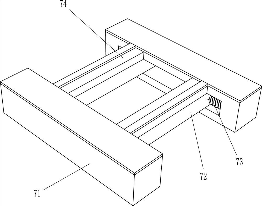
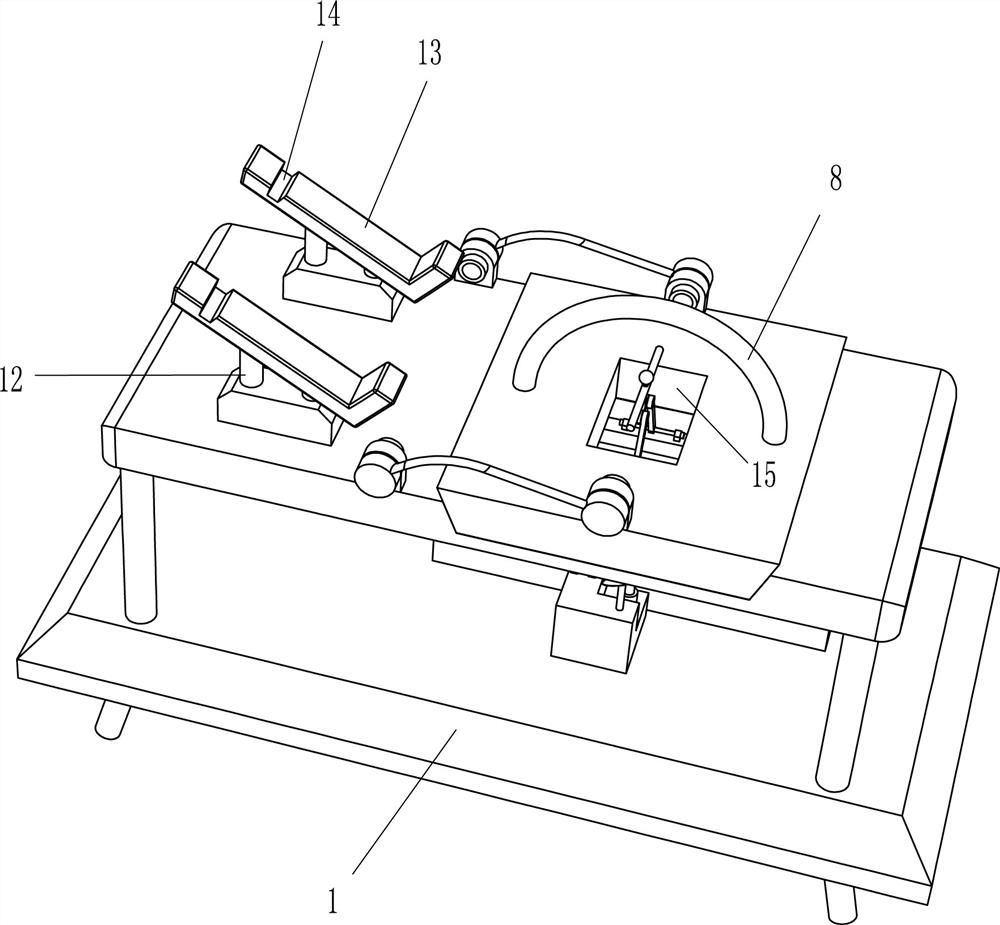
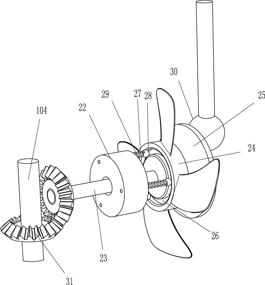
[0024] Such as figure 1 , 2 , 3 and shown, a grinding and cleaning equipment for electronic components feet, including a base 1, a workbench 2, a mounting seat 3, a rotating shaft 4, a connecting frame 5, a turning plate 6, a clamping mechanism 7, a handle 8, a grinding The mechanism 10 and the collection box 11, the top of the base 1 is provided with a workbench 2, the middle part of the trapezoidal chute on the workbench 2 is provided with a square hole 9, and the left side of the workbench 2 is symmetrically arranged with a mounting seat 3, two mounting seats 3 A rotating shaft 4 is provided, and a connecting frame 5 is arranged in a rotating manner on the two rotating shafts 4, and an overturning plate 6 is arranged between the left ends of the two connecting frames 5, and the overturning plate 6 is matched with the trapezoidal chute on the workbench 2, and the overturning plate 6 The middle part of the side that cooperates with the trapezoidal chute on the workbench 2 is...

Embodiment 2

[0029] On the basis of Example 1, such as figure 2 , 4, 5 and 6, also include support 12, L-shaped placement frame 13, rotating rod 151, connecting rod 16, connecting block 17, moving rod 18, top ball 19, fixed rod 20 and second elastic member 21, work The left side of the top of the table 2 is symmetrically arranged with brackets 12 by means of welding, and the tops of the two brackets 12 are provided with L-shaped placement racks 13, and the L-shaped placement racks 13 are inclined towards the direction of the square hole 9. Draw-in slot 14, square hole 15 is arranged in the middle part of turnover plate 6, and slide block 72 is provided with rotating rod 151 symmetrically near the side of square hole 15, and the middle part of two rotating rods 151 is connected with connecting rod 16 in a rotating manner, between the other ends of the two connecting rods 16. The connecting block 17 is provided with a rotating type, the middle part of the connecting block 17 is provided wi...


PUM


Abstract

The invention relates to a grinding and cleaning equipment, in particular to a grinding and cleaning equipment for the feet of electronic components. The technical problem of the present invention is to provide a clean, stable and safe grinding and cleaning equipment for the feet of electronic components. A foot grinding and cleaning equipment for electronic components comprises a base, a workbench is arranged on the top of the base, a square hole is opened in the middle of a trapezoidal chute on the workbench; There is a mounting seat; a rotating shaft, the two mounting seats are provided with a rotating shaft; a connecting frame, a connecting frame is rotatably arranged on the two rotating shafts; The trapezoidal chute clearance fit. The invention achieves the effects of clean grinding, stability and safety.

Description

technical field [0001] The invention relates to a grinding and cleaning device, in particular to a grinding and cleaning device for feet of electronic components. Background technique [0002] After the electronic components are welded on the PC board, the staff needs to use tools to clean or clean the feet of the electronic components. The staff first needs to polish the feet of the electronic components. The staff needs to start the grinding parts to rotate, and then the staff manually Contact the exposed feet of the electronic components on the PC board with the grinding parts, and the grinding parts can polish the feet of the electronic components. [0003] It can be seen from this that if the staff holds the PC board with the electronic component feet in contact with the grinding parts, it is easy to shake, easy to polish incompletely, or cause damage to the PC board, the efficiency is low, and there are safety problems. [0004] Therefore need to research and develop ...

Claims


Application Information

Patent Timeline
Patent Type & Authority Patents(China)
IPC IPC(8): B24B27/033B24B41/06B24B41/00B24B55/02B24B55/06
CPCB24B27/033B24B41/005B24B41/06B24B55/02B24B55/06
Inventor 不公告发明人
Owner 威海仁昌电子有限公司
Learn More