Furniture maintenance device

A furniture and intermediate position technology, which is applied to grinding drive devices, grinding/polishing safety devices, manufacturing tools, etc. The effect of maintenance in place, smooth polishing, and brightness improvement

Inactive Publication Date: 2020-12-25
广东斗擎网络科技有限公司
View PDF0 Cites 0 Cited by
  • Summary
  • Abstract
  • Description
  • Claims
  • Application Information

AI Technical Summary

Problems solved by technology

[0003] After the production and sales of solid wood furniture, the long-term use and wear of the users will cause defects and loss of luster in the solid wood furniture. At this time, the process of maintenance is required. It is fixed and stable, and the offset cannot be adjusted, which makes the grinding comfort not good, and it is not convenient to adjust various grinding angles

Method used


Image

  • Furniture maintenance device
  • Furniture maintenance device
  • Furniture maintenance device

Examples


Embodiment 1

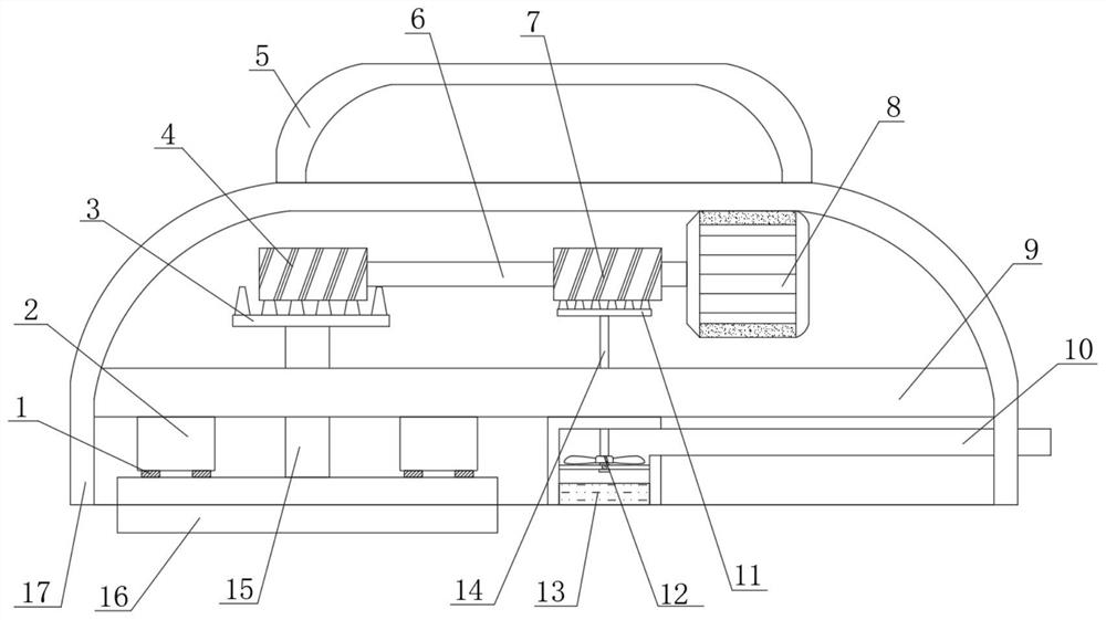
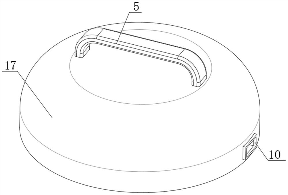
[0028]A furniture maintenance device, such asFigure 1-3 As shown, the main frame 17 is included. The central position of the inner circumferential wall of the main frame 17 is fixed with a horizontal fixed middle plate 9 through bolts, and one end of the top inner wall of the main frame 17 is fixed with a horizontally arranged electric motor 8 through bolts. The shaft is fixed with a horizontal rotating central shaft 6, one end of the circumferential outer wall of the rotating central shaft 6 is sleeved with a horizontally arranged driving screw 4, and one end between the top and bottom of the fixed middle plate 9 is provided with a first hole, and The inner circumferential wall of the first hole is sleeved with a driving rod 15, and a horizontal bevel gear 3 is fixed on the top of the driving rod 15. The top of the bevel gear 3 meshes with the circumferential outer wall of the driving screw 4 to drive the rotation The bottom position of the rod 15 is fixed with a horizontal grindin...

Embodiment 2

[0032]A furniture maintenance device, such asFigure 1-4As shown, the other end of the output shaft of the motor 8 is fixed with a vertically arranged drive gear 21, and the other end of the top and bottom of the fixed middle plate 9 is provided with a third hole, and the third hole is sleeved with a vertically arranged driving gear. Rod three 24, the top of the driving rod three 24 is fixed with a horizontally arranged rotating gear 22, and the rotating gear 22 meshes with the driving gear 21, the bottom of the driving rod three 24 is fixed with a horizontally arranged polishing disc 25, and ash is discharged The bottom end of the pipe 10 is fixed with a horizontally arranged liquid outlet plate 26, and the top of one end of the main box 17 is fixed with a vertically arranged liquid inlet pipe 23, and the bottom of the liquid inlet pipe 23 is sleeved with the liquid outlet plate 26.

[0033]When this embodiment is in use, a horizontal polishing disk 25 is installed at the other end of ...


PUM


Abstract

The invention belongs to the technical field of furniture maintenance, particularly relates to a furniture maintenance device, and provides the following scheme for solving the problem that a polishing disc of existing furniture maintenance equipment is fixed stably and cannot be adjusted. The furniture maintenance device comprises a main machine box, wherein a horizontally-arranged fixed middle plate is fixed in the middle of the circumferential inner wall of the main machine box through bolts, a horizontally-arranged motor is fixed to one end of the inner wall of the top of the main machinebox through bolts, and a horizontally-arranged rotating middle shaft is fixed to an output shaft of the motor. According to the furniture maintenance device, a vertically-arranged fixed machine box isinstalled at the bottom of the fixed middle plate, the interior of the fixed machine box is integrally connected with a vertical lifting block through a damping spring and an air spring, a rotating roller seat at the bottom of the lifting block can rotate along with the top of a polishing chassis, when an operator carries out pressing polishing, the polishing chassis at the bottom can carry out the micro-motion process, smooth polishing and angle changing are achieved, and polishing maintenance is more in place.

Description

Technical field[0001]The invention relates to the technical field of furniture maintenance, in particular to a furniture maintenance device.Background technique[0002]Solid wood furniture refers to furniture made of solid wood. Generally, solid wood furniture is divided into pure solid wood furniture and all solid wood furniture. Solid wood furniture is divided into beech, teak, maple, oak, red chrysanthemum, ash, elm, poplar, pine, etc. according to the wood materials. Among them, beech, teak and red chuck are the most valuable[0003]After the production and sales of solid wood furniture, the long-term use and wear of the users caused the solid wood furniture to produce defects and lack of gloss. At this time, the process of maintenance is required. However, the current polishing and maintenance devices are in use due to the grinding disc The fixation is stable, and the offset can not be adjusted, which makes the comfort of polishing poor and inconvenient for the adjustment of variou...

Claims


Application Information

Patent Timeline
Patent Type & Authority Applications(China)
IPC IPC(8): B24B23/02B24B41/04B24B47/12B24B55/10
CPCB24B23/02B24B41/04B24B47/12B24B55/102
Inventor 杨亚斯宋永兴宋元
Owner 广东斗擎网络科技有限公司
Why Eureka
Try Eureka