Brass rod machining continuous casting device

A brass rod and continuous casting technology, applied in the field of metal processing, can solve problems such as decreased processing efficiency

Inactive Publication Date: 2020-10-02
GUIXI AOTAI COPPER IND
View PDF10 Cites 0 Cited by
  • Summary
  • Abstract
  • Description
  • Claims
  • Application Information

AI Technical Summary

Problems solved by technology

[0004] The object of the present invention is to provide a continuous casting device for processing brass rods, to solve the problem that the continuous casting rollers of the existing continuous casting device proposed in the above background technology need to be lubricated in time during the long-term use to prevent continuous casting The problem that the operation of the roller is stuck, which leads to a decrease in processing efficiency

Method used


Image

  • Brass rod machining continuous casting device
  • Brass rod machining continuous casting device
  • Brass rod machining continuous casting device

Examples


Embodiment 1

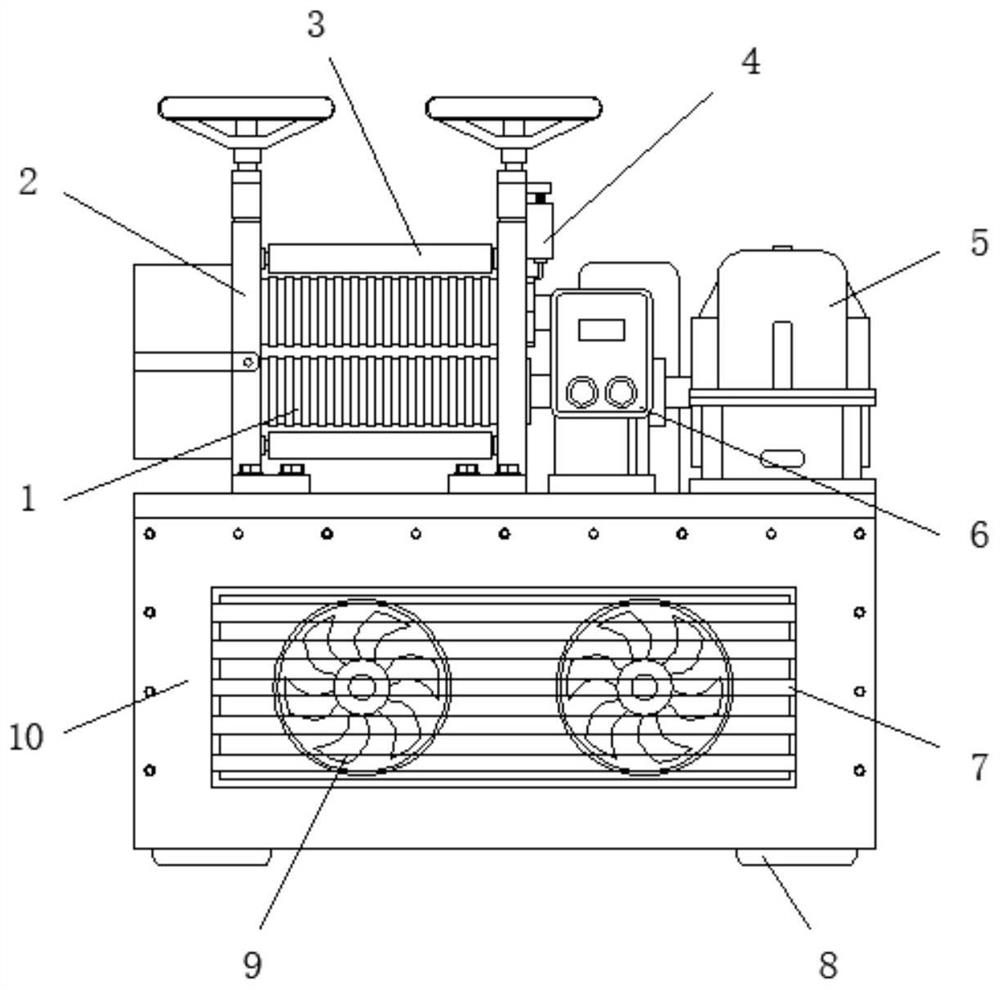
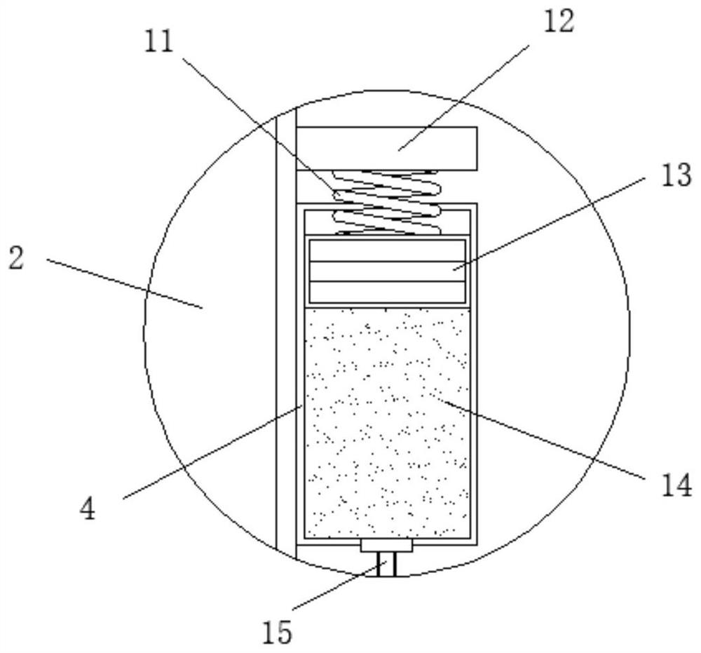
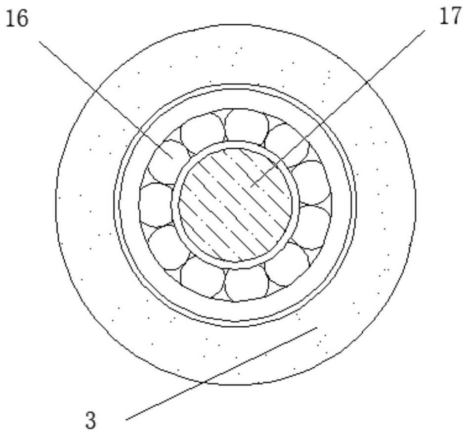
[0027] see figure 1 , figure 2 , image 3 with Figure 4 , the present invention provides a technical solution: a continuous casting device for processing brass rods, comprising a continuous casting body 10, the top side of the continuous casting body 10 is fixedly connected with a fixed frame 2, and the inner wall of the fixed frame 2 is fixedly connected with a continuous Casting roller 1, continuous casting main body 5 is fixedly connected to the other side of the top of continuous casting machine body 10, lubricating sleeve 4 is fixedly connected to the outside of the top end of fixed frame 2, and lubricating oil cotton 14 is fixedly connected to the inside of lubricating sleeve 4, The bottom surface of the lubricating sleeve 4 is fixedly connected with an oil delivery conduit 15 , the oil delivery conduit 15 communicates with the inside of the lubricating sleeve 4 , and the other end of the oil delivery conduit 15 is fixed on the end axis of the continuous casting drum...

Embodiment 2

[0038] see figure 1 , figure 2 , image 3 with Figure 5 , the present invention provides a technical solution: a continuous casting device for processing brass rods, comprising a continuous casting body 10, the top side of the continuous casting body 10 is fixedly connected with a fixed frame 2, and the inner wall of the fixed frame 2 is fixedly connected with a continuous Casting roller 1, continuous casting main body 5 is fixedly connected to the other side of the top of continuous casting machine body 10, lubricating sleeve 4 is fixedly connected to the outside of the top end of fixed frame 2, and lubricating oil cotton 14 is fixedly connected to the inside of lubricating sleeve 4, The bottom surface of the lubricating sleeve 4 is fixedly connected with an oil delivery conduit 15 , the oil delivery conduit 15 communicates with the inside of the lubricating sleeve 4 , and the other end of the oil delivery conduit 15 is fixed on the end axis of the continuous casting drum...


PUM


Abstract

The invention discloses a brass rod machining continuous casting device. The brass rod machining continuous casting device comprises a continuous casting machine body, a fixing frame is fixedly connected to one side of the top of the continuous casting machine body, a continuous casting roller is fixedly connected to the inner wall of the interior of the fixing frame, a continuous casting body isfixedly connected to the other side of the top of the continuous casting machine body, a lubricating sleeve is fixedly connected to the outer side of the top end of the fixing frame, lubricating oil cotton is fixedly connected into the lubricating sleeve, an oil conveying guide pipe is fixedly connected to the surface of the bottom of the lubricating sleeve, the oil conveying guide pipe communicates with the interior of the lubricating sleeve, and the other end of the oil conveying guide pipe is fixed to the axis of the end part of the continuous casting roller. Through the designed lubricating sleeve, lubricating oil cotton and the designed oil conveying guide pipe, a fixing spring deforms along with operation of the continuous casting device to push a piston, the piston conveys lubricating oil contained in the lubricating oil cotton to the axis of the continuous casting roller through the oil conveying guide pipe, and the continuous casting device continuously lubricates the continuous casting roller in an operation process.

Description

technical field [0001] The invention belongs to the technical field of metal processing, and in particular relates to a continuous casting device for processing brass rods. Background technique [0002] Brass rod is a rod-shaped object made of an alloy of copper and zinc. It is named for its yellow color. Brass with a copper content of 56%-68% has a melting point of 934-967 degrees. Brass has excellent mechanical properties and wear resistance. The performance is very good, and it can be used to manufacture precision instruments, parts of ships, shell casings of guns, etc. Currently, the continuous casting devices for processing brass rods that appear on the market still have various deficiencies and cannot meet the needs of production and life. . [0003] For example, in the existing continuous casting device, the continuous casting roller needs to be lubricated in time during the long-term use to prevent the operation of the continuous casting roller from being stuck and ...

Claims


Application Information

Patent Timeline
IPC IPC(8): B22D11/14B22D11/07B22D11/055
CPCB22D11/004B22D11/055B22D11/07B22D11/14
Inventor 孙锋
Owner GUIXI AOTAI COPPER IND
Why Eureka
Try Eureka