

Integrated battery bead frame and its connection structure with battery
A connection structure and battery technology, applied in the field of auto parts, can solve problems such as inconvenient installation, and achieve the effect of convenient installation, simple and reliable process
- Summary
- Abstract
- Description
- Claims
- Application Information
AI Technical Summary
Problems solved by technology
Method used
Image

Examples
Embodiment 1
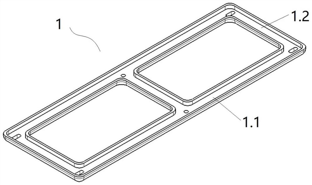
[0028] This embodiment discloses an integrated battery bead frame 1, which includes two compression beams 1.1, and a compression longitudinal beam 1.2 located between the two compression beams 1.1, wherein the compression beams 1.2 The longitudinal axis direction of the longitudinal beam 1.2 is perpendicular to the longitudinal axis direction of the compression beam 1.1, and both ends of the compression longitudinal beam 1.2 are fixedly connected to the compression beam 1.1 respectively. At the same time, the compression longitudinal beam 1.2 is located in the Compression beam 1.1 the position of the midpoint in the length direction. Through the integrated arrangement between the compression beam 1.1 and the compression longitudinal beam 1.1, the loosening of any compression beam can be effectively prevented, and at the same time, it is faster to fix and install the battery and the fixing frame.
Embodiment 2
[0030] This embodiment discloses an integrated battery bead frame 1, such as figure 1 shown, it comprises two compression beams 1.1, and three compression beams 1.2 between the two compression beams 1.1, wherein the longitudinal axis of each compression beam 1.2 is perpendicular to the direction of the longitudinal axis of the compression beam 1.2. The compression beam 1.1 is in the longitudinal axis direction, and the two ends of each compression beam 1.2 are fixedly connected to the compression beam 1.1, and one of the compression beams 1.2 is located in the longitudinal direction of the compression beam 1.1. The midpoint connection position , the remaining two compression longitudinal beams 1.2 are respectively arranged at the longitudinal ends of the compression beams 1.1. Among them, in the present invention, it is preferred that the three compression longitudinal beams 1.2 and the two compression transverse beams 1.1 are integrated design, and the battery can be fixed mo...
Embodiment 3
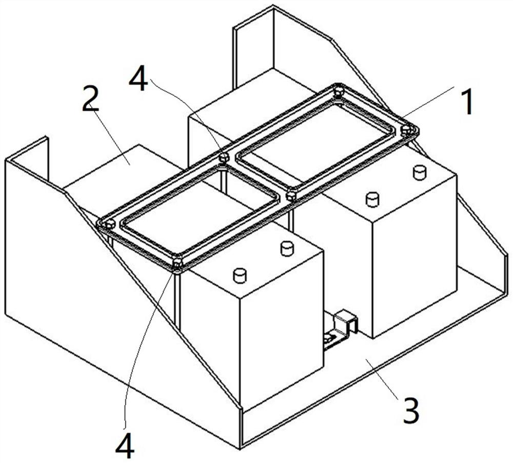
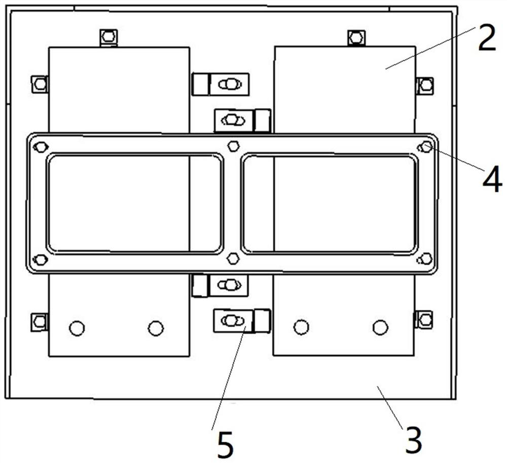
[0032] The invention discloses a connection structure of an integrated battery bead frame and a battery, such as figure 2 , image 3 As shown, it includes a fixing plate 3 on the outside of the battery 2, one or more connecting rods 4 perpendicular to the fixing plate 3, and more than one stopper 5 arranged on the fixing plate 3, each of which is The compression beam 1.1 and the compression longitudinal beam 1.2 are close to the outer wall of the battery 2 and are connected to the fixing plate 3 through the connecting rod 4 to realize the fixing and limiting of the battery. Similarly, in order to realize the fixing of each connecting rod 4, the present invention It is also selected that the fixing plate 3 is provided with through holes corresponding to the connecting rods 4, which are not described in detail in the present invention, but are still within the protection scope of the present invention.
[0033] combine Figure 4 As shown, the limiting member 5 includes a limi...
PUM
 Abstract
Description
Claims
Application Information