A control circuit for safe mite removal electric blanket that meets electromagnetic compatibility requirements

A technology of electromagnetic compatibility and control circuit, used in electric heating devices, ohmic resistance heating, blankets, etc., can solve the problems of human injury, high temperature in removing mites, etc., and achieve the effect of avoiding low-temperature scald or heat stroke injury

Active Publication Date: 2022-05-13
成都彩虹电器(集团)股份有限公司
View PDF6 Cites 0 Cited by
  • Summary
  • Abstract
  • Description
  • Claims
  • Application Information

AI Technical Summary

Problems solved by technology

[0005] Aiming at the problem of electromagnetic compatibility in the above-mentioned prior art and the problem that the high temperature of mite removal may cause harm to the human body, this application proposes a mite removal electric heater that meets the requirements of the national electromagnetic compatibility (EMC) standard and can be safely touched by the human body. blanket control circuit

Method used


Image

  • A control circuit for safe mite removal electric blanket that meets electromagnetic compatibility requirements

Examples


Embodiment 1

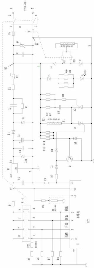
[0029] Such as figure 1 As shown, a safe anti-mite electric blanket control circuit that meets the requirements of electromagnetic compatibility includes a power supply circuit, a single-chip microcomputer control circuit, a trigger circuit, a power control circuit, and a double-pole single-throw structure. -1), protection circuit and display circuit; wherein the power circuit is connected with the single-chip control circuit and the trigger circuit; the single-chip control circuit is connected with the trigger circuit and the power control circuit; the switch K1-1 is connected with the single-chip control circuit; the switch K1 is connected with the power circuit, The power control circuit is connected to the trigger circuit; the display circuit is connected to the power circuit; the power circuit is connected to the heating element through the main thyristor V1 and the slave thyristor V2 in the power control circuit, and the protection circuit is connected to the power circui...

Embodiment 2

[0038] Such as figure 1 As shown, a safe anti-mite electric blanket control circuit that meets electromagnetic compatibility requirements includes a power supply circuit, a single-chip microcomputer control circuit, a trigger circuit, a power control circuit, and a double-pole single-throw structure. 1), protection circuit, display circuit.

[0039] The single-chip microcomputer in the single-chip microcomputer control circuit has preset control programs for four gears: mite removal, preheating, heat preservation, and sleep, among which:

[0040] Mite removal program: The average heating rate is 0.9°C / min, and the temperature rises to a constant temperature of 43°C. Measure the humidity at the same time as the temperature rises. When the humidity drops to 45%, continue to dehumidify at a constant temperature and start timing. After 100 minutes, start to cool down: the cooling rate is 1°C every 15 minutes until it drops to 36°C. Keep the temperature constant and dry, and set t...


PUM


Abstract

This application relates to the field of electric blanket production, specifically a control circuit for a safe mite removal electric blanket that satisfies electromagnetic compatibility requirements, wherein the power circuit is connected to a single-chip microcomputer control circuit and a trigger circuit; the single-chip microcomputer control circuit is connected to a trigger circuit and a power control circuit connected; the display circuit is connected in parallel with the switch; the power supply circuit is connected to the heating element through the main thyristor V1 and the slave thyristor V2 in the power control circuit, and the protection circuit is connected to the power supply circuit at the same time. In this application, while applying the parallel connection of varistor and capacitor to absorb pulse interference, a self-recovery fuse is connected in series in the power supply circuit to block the large current formed by pulse interference lower than the limit value of varistor; The half-wave gate circuit realizes the zero-crossing trigger, which avoids interference to the grid environment; the combination of human body contact with safe temperature and dehumidification and drying realizes mite removal, which avoids low-temperature burns or heat stroke injuries that may be caused by high-temperature mite removal.

Description

technical field [0001] This application relates to the field of electric blanket production, in particular to a control circuit for a safe mite-removing electric blanket that meets electromagnetic compatibility (EMC) requirements. Background technique [0002] When the existing ordinary electric blanket or anti-mite electric blanket is in working condition, its control circuit may appear abnormal operation or even damage when it is subjected to electromagnetic interference; and the ordinary electric blanket or anti-mite electric blanket may even appear Harassment that is not allowed by the national standard. In particular, in the prior art, the combination of piezoresistor and capacitor is used to absorb the pulse interference of the power grid. The circuit cannot block the continuous pulse interference less than the limit voltage of the piezoresistor, and cannot fully protect the low-voltage electronic components commonly used in the circuit. , technical flaws are obvious....

Claims


Application Information

Patent Timeline
Patent Type & Authority Patents(China)
IPC IPC(8): H05B1/02A47G9/02H05B3/34
CPCH05B1/0272H05B3/342A47G9/0215A47G2009/001
Inventor 田鹏万昌斌何洁张博文杨汉宗谭雷
Owner 成都彩虹电器(集团)股份有限公司
Why Eureka
Try Eureka