Three-knife trimmer

A surface cutting and countertop technology, applied in metal processing, etc., can solve the problems of rapid blade replacement, long downtime, long replacement time, etc., and achieve fast and efficient tool change, high degree of automation, and high transfer speed.

Active Publication Date: 2020-10-09
浙江合为机械有限公司
View PDF5 Cites 7 Cited by
  • Summary
  • Abstract
  • Description
  • Claims
  • Application Information

AI Technical Summary

Problems solved by technology

[0003] The current three-side trimming machine usually includes a book feeding device, which is used to send a stack of books to the cutting device as a whole; a countertop book alignment device, which organizes a stack of books; The side and front of the book are cut to make the overall size of the book uniform, and a cutting area is formed at the cutting device. There is also a paper pressing mechanism above the cutting area, which is used to press a stack of books tightly to prevent the book from being cut. Shifting occurs during cutting; and a book push-out device, which is used to remove the cut books for collection; wherein the blade of the cutting device needs to be replaced after being worn for a period of time, and a new (ground) blade needs to be replaced , usually the replacement time is long, the downtime is long, and there is currently no structure for quick blade replacement

Method used


Image

  • Three-knife trimmer
  • Three-knife trimmer
  • Three-knife trimmer

Examples


Embodiment Construction

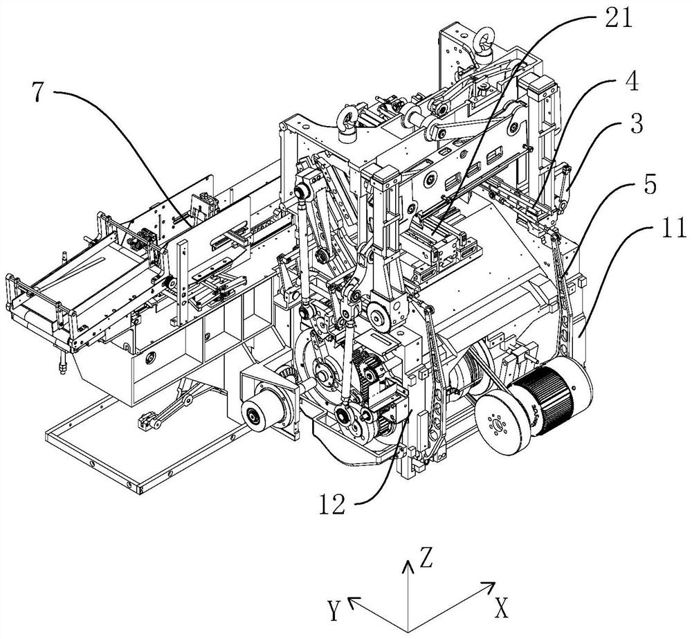
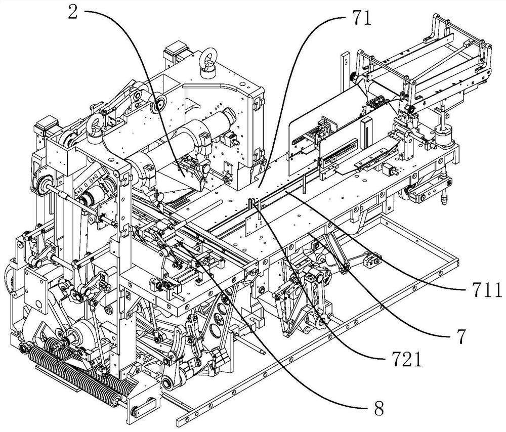
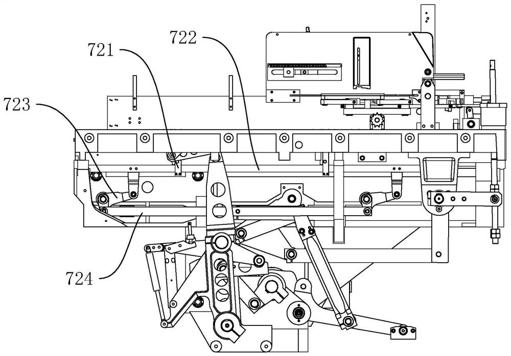
[0036] refer to Figure 1 to Figure 14 The embodiment of the three-side trimmer of the present invention will be further described.

[0037] In the description of the present invention, it should be noted that for orientation words, such as the term "center", "horizontal (X)", "longitudinal (Y)", "vertical (Z)", "length", " Width", "Thickness", "Top", "Bottom", "Front", "Back", "Left", "Right", "Vertical", "Horizontal", "Top", "Bottom", "Inner ", "outside", "clockwise", "counterclockwise" and other indication orientations and positional relationships are based on the orientation or positional relationship shown in the drawings, and are only for the convenience of describing the present invention and simplifying the description, rather than indicating or implying the Means that a device or element must have a specific orientation, be constructed and operated in a specific orientation should not be construed as limiting the specific protection scope of the present invention.

...


PUM


Abstract

The invention discloses a three-knife trimmer. The trimmer comprises a book conveying device, a table top stop alignment device, a cutting device and a book push-out device, wherein the cutting devicecomprises a knife seat, a knife jig and a blade, wherein the blade is fixed on the knife jig, a lower supporting body and an upper supporting body are arranged on one side of the knife seat, a mounting groove is formed between the lower supporting body and the upper supporting body, a lower dovetail groove is formed between the lower supporting body and the knife seat, an upper dovetail groove isformed between the upper supporting body and the knife seat, the lower surface of the upper supporting body is inclined in a transverse direction from one side to the other side, a mounting inclinedblock is arranged on the knife jig, the mounting inclined block extends into the mounting groove, the shape of the bottom surface of the mounting inclined block is the same as the lower dovetail groove, the shape of the top surface of the mounting inclined block is the same as the upper dovetail groove, a locking mechanism is arranged on the knife seat, and the locking mechanism squeezes and fixesthe knife jig in the mounting groove. According to the trimmer, the blade can be rapidly changed after being worn, the changed blade can reach a designated position to be fixed, and accuracy is veryhigh.

Description

technical field [0001] The invention belongs to the field of shredders, and more specifically relates to a three-side shredder. Background technique [0002] Due to the large number of books printed, in order to facilitate the consistency of the length and width of a large number of books after printing, a three-side trimmer is used. This kind of three-side trimmer places the books horizontally on the operating platform and uses a three-side trimmer. The two side knives of the book machine cut the length of the book, and the front knife cuts the width of the book. At present, there are many three-side shredders on the market. One of the most commonly used three-side shredders is to install side knives and front knives on the knife holder. Books will be cut into books of uniform length. [0003] The current three-side trimming machine usually includes a book feeding device, which is used to send a stack of books to the cutting device as a whole; a countertop book alignment ...

Claims


Application Information

Patent Timeline
Patent Type & Authority Applications(China)
IPC IPC(8): B26D7/02B26D7/06B26D7/26B26D7/32
CPCB26D7/025B26D7/06B26D7/2614B26D7/32
Inventor 张杰李凤其周尉强张健纪一平
Owner 浙江合为机械有限公司
Why Eureka
Try Eureka