
An installation tool for automatic guiding and limiting of steel wire retaining ring for holes

A technology for steel wire retaining rings and installation tools, which is applied in the field of tooling assembly, can solve the problems of large compression deformation of steel wire retaining rings, poor positioning effect, and difficult operation, etc., and achieve the effect of accurate center positioning, reliable quality and lower skill level

Active Publication Date: 2021-09-28
北京力威尔航空精密机械有限公司
View PDF8 Cites 0 Cited by
  • Summary
  • Abstract
  • Description
  • Claims
  • Application Information

AI Technical Summary

Problems solved by technology

[0003] At present, the existing installation tools have problems such as poor positioning effect, large compression deformation of the steel wire retaining ring, difficult operation during installation and use, and adjustment after installation.

Method used


Image

  • An installation tool for automatic guiding and limiting of steel wire retaining ring for holes
  • An installation tool for automatic guiding and limiting of steel wire retaining ring for holes
  • An installation tool for automatic guiding and limiting of steel wire retaining ring for holes

Examples


Embodiment Construction

[0038] In order to make the purpose, technical solutions and advantages of the embodiments of the present invention more clear, the technical solutions in the embodiments of the present invention will be clearly and completely described below in conjunction with the drawings in the embodiments of the present invention. Apparently, the described embodiments are some, not all, embodiments of the present invention. Based on the embodiments of the present invention, all other embodiments obtained by persons of ordinary skill in the art without making creative efforts belong to the protection scope of the present invention.

[0039] The features of various aspects of the embodiments of the present invention will be described in detail below. In the following detailed description, numerous specific details are set forth in order to provide a thorough understanding of the present invention. It will be apparent, however, to one skilled in the art that the present invention may be pra...


PUM


Abstract

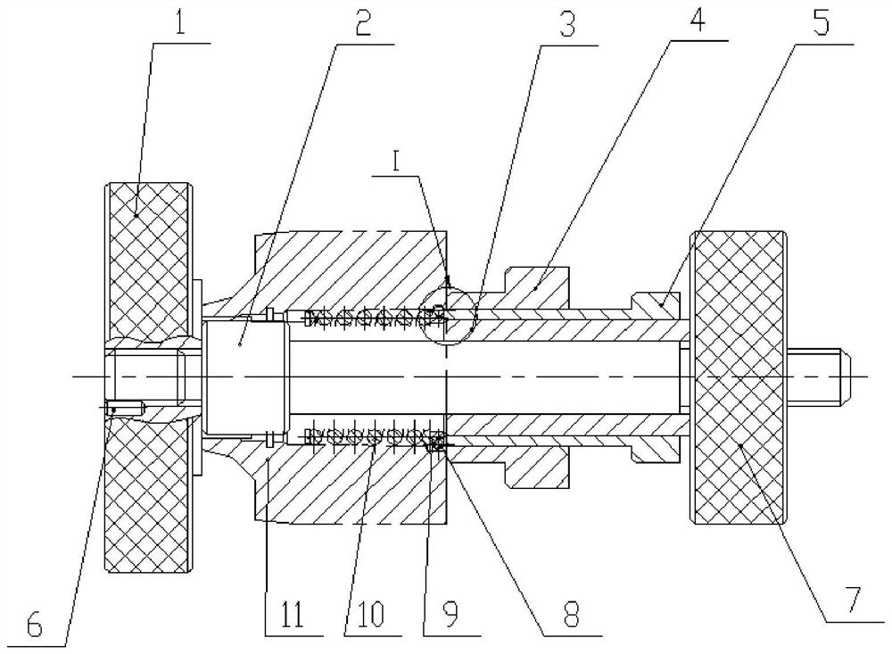
The invention belongs to the technical field of tooling assembly, and relates to an installation tool for automatically guiding and limiting a steel wire retaining ring for a hole, comprising an end seat (1), a screw rod (2), a pressure sleeve (3), a guide sleeve (4), and an installation sleeve (5), pin (6), nut (7); the smooth surface of the right end of the end seat (1) is used for part positioning, the screw (2) and pin (6) are installed on the end seat (1), and the pressure sleeve (3) Set on the screw rod (2), limit the installation sleeve (5), the installation sleeve (5) limit the guide sleeve (4), the guide sleeve (4) limit the steel wire retaining ring, the nut (7) It is installed on the screw rod (2) through threaded connection, and the pressure sleeve (3) and the installation sleeve (5) are driven by the screw transmission between the two to realize the assembly of the steel wire retaining ring. Utilize the transfer positioning guide between the positioning shaft and the positioning sleeve, and convert the helical movement of the thread into axial displacement and compression, so as to realize the compression of the spring seat and spring and the positioning and movement of the wire retaining ring.

Description

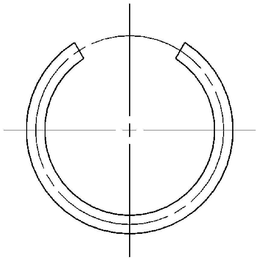
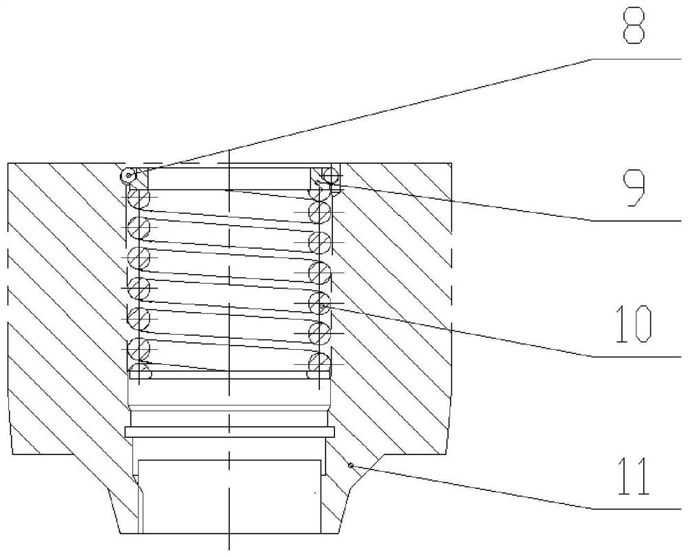
technical field [0001] The invention belongs to the field of tooling assembly technology, and relates to the assembly technology of a hydraulic mechanical actuator of an aero-engine fuel control system, in particular to an installation tool for automatic guiding and positioning of a steel wire retaining ring for a hole, which can realize rapid positioning and installation. Background technique [0002] The retaining ring, also known as the retaining ring, is divided into the retaining ring for the hole and the retaining ring for the shaft, which acts as an axial limit and can prevent other parts from moving axially. For general retaining rings, snap ring pliers can be used to install them, while wire retaining rings (schematic diagram as figure 1 As shown) there is no good point of force, the elasticity is small, and it is easy to slip or even break with ordinary installation methods, and may damage the assembly parts. When assembling, the spring 10 and the spring seat 9 nee...

Claims


Application Information

Patent Timeline
Patent Type & Authority Patents(China)
IPC IPC(8): B25B27/30
CPCB25B27/30
Inventor 李崇李学明喻阳
Owner 北京力威尔航空精密机械有限公司
Learn More