Die-cutting machine
A die-cutting machine and die-cutting technology, which is applied in the directions of sending objects, thin material handling, transportation and packaging, and can solve the problems of unclean edge removal, label waste, breakage, etc.
- Summary
- Abstract
- Description
- Claims
- Application Information
AI Technical Summary
Problems solved by technology
Method used
Image


Examples
Embodiment 1
[0022] as attached figure 1 to attach Figure 4 Shown:
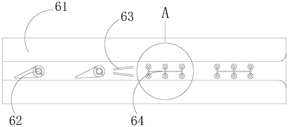
[0023] The present invention is a kind of die-cutting machine, and its structure comprises die-cutting host machine 1, unwinding roller 2, conveyer 3, control panel 4, waste material rewinding roller 5, stripping mechanism 6, anti-breakage mechanism 7, rewinder 8, all An unwinding roller 2 is installed on the front surface of the left end of the die-cutting host 1, and a conveyor 3 is arranged at the middle end of the front surface of the die-cutting host 1, and the conveyor 3 is located on the right side of the unwinding roller 2, and the front surface of the conveyor 3 The control panel 4 is fixedly installed and electrically connected. The waste material winding roller 5 is installed at the middle end of the front surface of the die-cutting host 1, and the waste material winding roller 5 is located above the conveyor 3, and the conveyor 3 is provided with a stripping mechanism inside 6. The lower end of the anti-bre...
Embodiment 2
[0029] as attached Figure 5 to attach Figure 7 Shown:
[0030] Wherein, the anti-break mechanism 7 includes a lifting mechanism 71, a conductive plate 72, a sliding block 73, a rotating roller 74, and a compression mechanism 75. The lower end of the lifting mechanism 71 is fixedly installed on the upper end of the conveyor 3, and the conductive plate 72 is located at the upper end of the conveyor 3. The top of the lifting mechanism 71, the sliding block 73 is located at the front end of the lifting mechanism 71, the rotating roller 74 is installed inside the sliding block 73 with clearance fit, the compression mechanism 75 is fixedly installed on the front surface of the conductive plate 72, and the compression mechanism 75 is located at Above the rotating roller 74, the lifting mechanism 71 is provided with two in total, which are respectively located at the front and rear ends of the conduction plate 72, through the cavity formed between the conduction plate 72 and the tw...
PUM
 Abstract
Description
Claims
Application Information
 - R&D Engineer
- R&D Manager
- IP Professional
- Industry Leading Data Capabilities
- Powerful AI technology
- Patent DNA Extraction
Browse by: Latest US Patents, China's latest patents, Technical Efficacy Thesaurus, Application Domain, Technology Topic.
© 2024 PatSnap. All rights reserved.Legal|Privacy policy|Modern Slavery Act Transparency Statement|Sitemap