Electric power engineering distribution box

A power engineering and distribution box technology, applied in electrical components, substation/switch layout details, busbar/line layout, etc., can solve problems such as hidden safety hazards, limited distribution box space, inconvenient wiring operations, etc., to avoid wiring errors , to avoid cross confusion, and to facilitate the effect of wiring

Inactive Publication Date: 2020-10-09
安徽盛琛电力工程有限公司
5 Cites 0 Cited by

AI-Extracted Technical Summary

Problems solved by technology

When the existing distribution box is in use, due to the limited space of the distribution box, the wiring operat...

Method used

In the present invention, the upper wiring board 3 of the upper wiring assembly, the lower wiring board 4 two ends of the lower wiring assembly are all connected with the casing 1 inner wall sliding fit, when wiring, pull the upper wiring board 3, the lower wiring board 4 Move outward to the openi...

Abstract

The invention provides an electric power engineering distribution box, which comprises a box body and a box door connected with the box body, wherein an upper wiring assembly and a lower wiring assembly which are arranged up and down are installed in the box body; the upper wiring assembly comprises an upper wiring board, the upper wiring board is horizontally arranged and is parallel to the box door, two ends of the upper wiring board are in sliding fit connection with the inner walls of the box body, and an upper wiring clamp for fixing a cable is mounted on one side, close to the box door,of the upper wiring board; and the lower wiring assembly comprises a lower wiring board which is horizontally arranged and parallel to the box door, the two ends of the lower wiring board are in sliding fit connection with the inner walls of the box body, and a lower wiring clamp used for fixing a cable is installed on the side, close to the box door, of the lower wiring board. When wiring is carried out, the upper wiring board and the lower wiring board are pulled to move outwards to the opening positions, wiring is carried out, cables are fixed, then the upper wiring board and the lower wiring board are sent back into the box body, wiring is convenient, and wiring errors are avoided, thereby guaranteeing that the cables in the box body are kept orderly, and cross disorder is avoided.

Application Domain

Technology Topic

Image

  • Electric power engineering distribution box
  • Electric power engineering distribution box
  • Electric power engineering distribution box

Examples

  • Experimental program(1)

Example Embodiment

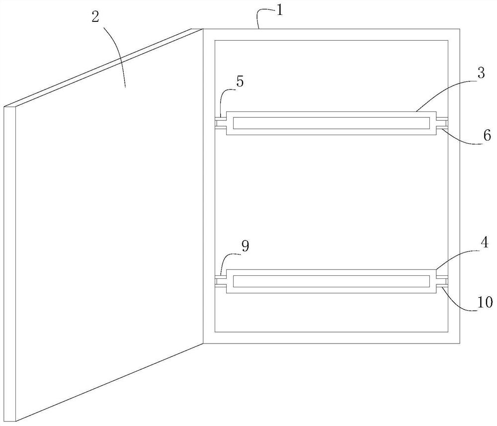
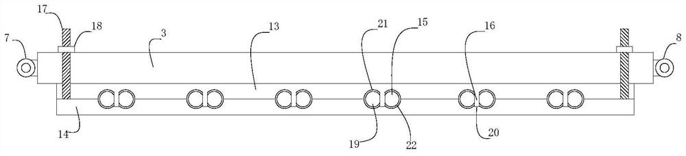
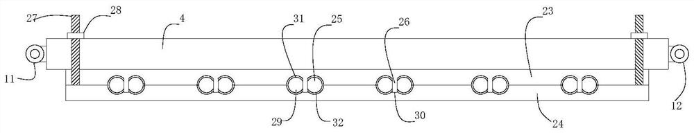
[0015] Reference Figure 1-Figure 3 , The present invention proposes a power engineering distribution box, including a box body 1 and a box door 2 connected to the box body 1; the box body 1 is installed with upper and lower wiring components arranged up and down; wherein:
[0016] The inner wall of the box body 1 is equipped with a first upper guide rail 5 and a second upper guide rail 6 arranged in parallel and oppositely and in the same horizontal plane. The first upper guide rail 5 and the second upper guide rail 6 are both perpendicular to the door 2 and the first upper guide rail 5 The end of the second upper guide rail 6 close to the door 2 is a free end. The inner wall of the box body 1 is also installed with a first lower guide rail 9 and a second lower guide rail 10 arranged in parallel and oppositely and in the same horizontal plane. The first lower guide rail 9 and the second lower guide rail 10 are both perpendicular to the door 2 and the first lower guide rail 9. Both ends of the second lower guide rail 10 close to the door 2 are free ends.
[0017] The upper wiring assembly includes an upper wiring board 3, which is arranged horizontally and parallel to the box door 2. Both ends of the upper wiring board 3 are equipped with a first upper roller 7 and a second upper roller 8, respectively. The first upper roller 7, the upper The second roller is slidably connected with the first upper rail 5 and the second upper rail 6 respectively, and an upper terminal clamp for fixing cables is installed on the side of the upper wiring board 3 close to the door 2.
[0018] The lower wiring assembly includes a lower wiring board 4, which is arranged horizontally and parallel to the box door 2. Both ends of the lower wiring board 4 are respectively installed with a first lower roller 11, a second lower roller 12, a first lower roller 11, a second lower roller The two lower rollers 12 are respectively connected to the first lower guide rail 9 and the second lower guide rail 10 in a sliding fit, and a lower terminal clamp for fixing cables is installed on the side of the lower wiring board 4 close to the door 2.
[0019] In the present invention, both ends of the upper wiring board 3 of the upper wiring assembly and the lower wiring board 4 of the lower wiring assembly are connected in sliding fit with the inner wall of the box body 1. When wiring, the upper wiring board 3 and the lower wiring board 4 are pulled to move outward After reaching the opening position, wiring and fixing the cables, return the upper wiring board 3 and lower wiring board 4 to the box 1, which not only facilitates wiring and avoids wiring errors, but also ensures that the cables inside the box 1 are kept in order. Avoid cross confusion.
[0020] In a specific embodiment, the upper splint includes a first upper splint 13 and a second upper splint 14. The first upper splint 13 is fixed on the upper splint 3, and the first upper splint 13 is provided on the side away from the upper splint 3. A first upper fixing group, the first upper fixing group includes two adjacently arranged first upper half grooves 15, the inner wall of the first upper half groove 15 is provided with a first upper non-slip rubber layer 21, two first upper half grooves An upper bobbin 16 perpendicular to the first upper clamping plate 13 and extending outward is arranged between 15. The second upper clamping plate 14 is located on the side of the first upper clamping plate 13 away from the upper wiring board 3, and the second upper clamping plates 14 are all provided with an upper screw 17 which passes through the first upper clamping plate 13, the upper wiring board 3 and the upper nut 18 is connected and the upper screw 17 is in clearance fit with the first upper clamping plate 13 and the upper wiring board 3. The second upper splint 14 is provided with a plurality of second upper fixing groups on the side close to the first upper splint 13, and the plurality of second upper fixing groups are respectively arranged in one-to-one correspondence with the plurality of first upper fixing groups, and the second upper fixing groups include Two adjacently arranged second upper half grooves 19, the inner wall of the second upper half groove 19 is provided with a second upper non-slip rubber layer 22, between the two second upper half grooves 19 is provided for the insertion of the upper winding column 16 The upper positioning groove 20, the two second upper half grooves 19 of the second upper fixing group and the two first upper half grooves 15 of the corresponding first upper fixing group are respectively assembled into upper cable grooves for cables to pass through. When wiring, turn the upper nut 18 to disengage the upper screw 17, adjust the distance between the first upper splint 13 and the second upper splint 14, and pass the cable through a first upper half groove 15 of the first upper fixing group Then, after bypassing the upper bobbin 16 and then passing through another first upper half groove 15, move the second upper splint 14 to the first upper splint 13 and lock the upper nut 18 on the upper screw 17 to make the upper winding The wire post 16 is inserted into the upper positioning slot 20 to clamp the cable, which is convenient for fixing the cable.
[0021] In a specific embodiment, the lower terminal clamp includes a first lower clamp plate 23 and a second lower clamp plate 24. The first lower clamp plate 23 is fixed on the lower terminal plate 4, and the first lower clamp plate 23 is provided with a plurality of The first lower fixing group, the first lower fixing group includes two adjacently arranged first lower half grooves 25, the inner wall of the first lower half groove 25 is provided with a first lower non-slip rubber layer 31, and two first lower half grooves 25 There is a lower bobbin 26 perpendicular to the first lower clamping plate 23 and extending outward. The second lower splint 24 is located on the side of the first lower splint 23 away from the lower wiring board 4, and the second lower splints 24 are provided with a lower screw 27. The lower screw 27 passes through the first lower splint 23, the lower wiring board 4 and the lower nut 28 is connected and the lower screw 27 is in clearance fit with the first lower clamping plate 23 and the lower wiring board 4. The second lower splint 24 is provided with a plurality of second lower fixing groups on the side close to the first lower splint 23, and the plurality of second lower fixing groups are respectively arranged in one-to-one correspondence with the plurality of first lower fixing groups, and the second lower fixing groups include Two adjacently arranged second lower half grooves 29, the inner wall of the second lower half groove 29 is provided with a second lower anti-slip rubber layer 32, between the two second lower half grooves 29 is provided for the insertion of the lower bobbin 26 The lower positioning groove 30, the two second lower half grooves 29 of the second lower fixing group and the corresponding two first lower half grooves 25 of the first lower fixing group are assembled into lower cable grooves for cables to pass through. When wiring, turn the lower nut 28 to disengage the lower screw 27, adjust the distance between the first lower splint 23 and the second lower splint 24, and pass the cable through a first lower half groove 25 of the first lower fixing group Then, after bypassing the lower winding column 26, pass through another first lower half slot 25, move the second lower clamping plate 24 to the first lower clamping plate 23 and lock the lower nut 28 on the lower screw 27 to make the lower winding The post 26 is inserted into the lower positioning slot 30 to clamp the cable to facilitate the fixing of the cable.
[0022] The above are only preferred specific embodiments of the present invention, but the protection scope of the present invention is not limited to this. Anyone familiar with the technical field within the technical scope disclosed by the present invention, according to the technical solution of the present invention The equivalent replacement or change of the inventive concept thereof shall be covered by the protection scope of the present invention.

PUM

no PUM

Description & Claims & Application Information

We can also present the details of the Description, Claims and Application information to help users get a comprehensive understanding of the technical details of the patent, such as background art, summary of invention, brief description of drawings, description of embodiments, and other original content. On the other hand, users can also determine the specific scope of protection of the technology through the list of claims; as well as understand the changes in the life cycle of the technology with the presentation of the patent timeline. Login to view more.

Similar technology patents

Classification and recommendation of technical efficacy words

Why Eureka
Try Eureka