Sliding equipment

A technology of equipment and pulley, applied in the field of sliding equipment, can solve the problems of heavy workload of staff and increase of equipment cost, and achieve the effect of good braking effect, reduction of construction cost, and safe and reliable operation.

Pending Publication Date: 2020-10-13
北京特伦斯科技开发有限公司
View PDF0 Cites 0 Cited by
  • Summary
  • Abstract
  • Description
  • Claims
  • Application Information

AI Technical Summary

Problems solved by technology

The existing sliding equipment mainly has the following defects: due to the fast sliding speed, a relatively long braking section is usually set according to

Method used


Image

  • Sliding equipment
  • Sliding equipment
  • Sliding equipment

Examples


Embodiment Construction

[0051] The principles and features of the present invention are described below, and the examples given are only used to explain the present invention, and are not intended to limit the scope of the present invention.

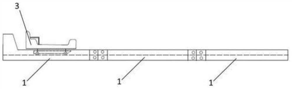
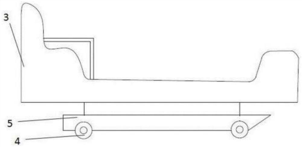
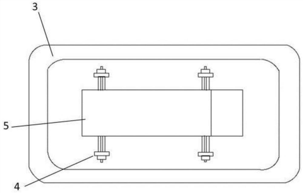
[0052] Such as Figure 1 to Figure 14 As shown, the present invention provides a sliding device, including a slideway and a pulley used in conjunction with the slideway; at least one pulley.

[0053] The slideway includes two rails 1 and at least one connecting bracket 2, at least one of the connecting brackets 2 is used to connect the two rails 1; the two rails 1 are parallel to each other, and the opposite one of the two rails 1 Each side has rail runners respectively.

[0054] Such as Image 6 with Figure 7 As shown, the track 1 includes a top wall 12, a side wall 13 and a bottom wall 14, one end of the bottom wall 14 is connected to the bottom end of the side wall, and the other end of the bottom wall 14 extends upwards and then approaches the side wall...


PUM


Abstract

The invention relates to sliding equipment. The sliding equipment comprises a slideway and at least one tackle, the slideway comprises two rails which are parallel to each other, and rail sliding grooves are formed in the opposite sides of the two rails respectively. The rail is divided into a starting section and a stopping section, a brake plate is arranged on the stopping section, the tackle isused in cooperation with the slideway, two sets of wheels of the tackle are rotationally arranged on the two sides of the bottom of the tackle body respectively, and a friction plate is located between the two sets of wheels and fixedly connected with the bottom face of the tackle body. The wheels are located in the rails and can roll along the rails. When the tackle runs to the stopping section,the upper surface of the brake plate abuts against the bottom face of the friction plate. The end, away from the starting section, of the track of the stopping section is provided with an opening section with the open top, and the included angle b between the rear end of the rubber steel wire layer and the ground is 25-40 degrees. The invention has the advantages of lower requirement on natural field, quickness, simplicity and convenience in installation, adjustable length, safety and reliability in operation, labor saving, short stop section, low cost and the like.

Description

technical field [0001] The invention relates to entertainment facilities, in particular to a sliding device. Background technique [0002] The existing sliding equipment adopts the combination of the block and the sliding track to ensure the running track of the block, and multiple people can slide at the same time without mutual interference. The end of the sliding track is equipped with a brake plate to decelerate and stop the block through friction. The existing sliding equipment mainly has the following defects: due to the high sliding speed, a longer braking section is usually set according to experience, resulting in an increase in equipment cost, and the trolley needs to be dragged to the end of the sliding track before it can be taken out. large. Contents of the invention [0003] The technical problem to be solved by the present invention is how to provide a sliding device with reasonable braking distance, good riding experience and high cost performance. [000...

Claims


Application Information

Patent Timeline
IPC IPC(8): A63G21/06
CPCA63G21/06
Inventor 王国安
Owner 北京特伦斯科技开发有限公司
Why Eureka
Try Eureka