Wire rod flat steel putting device

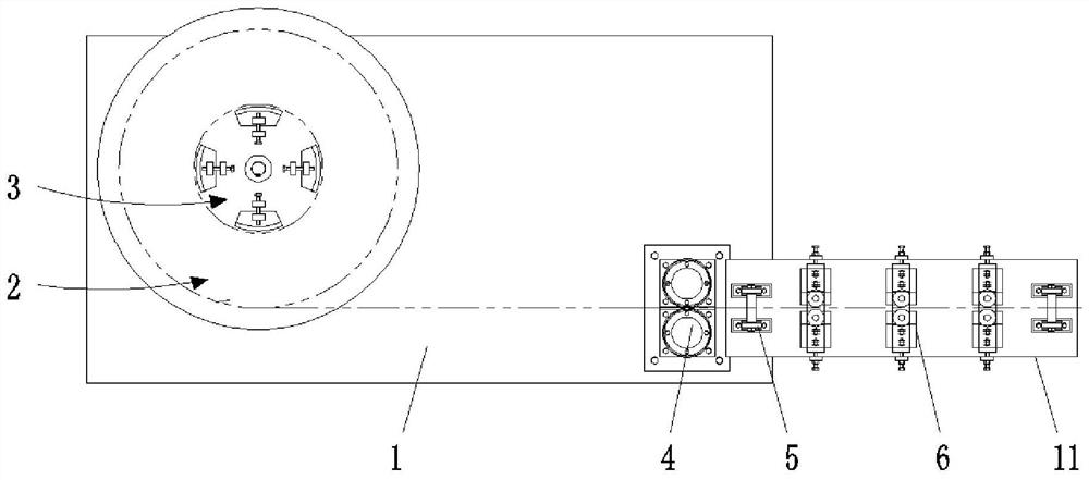
A technology of discharging device and flat steel is applied in the field of disc-round flat steel discharging device, which can solve problems such as inapplicability, and achieve the effects of convenient operation, favorable for popularization and application, and improvement of production efficiency.

Inactive Publication Date: 2020-10-13
XINXING ENERGY EQUIP
View PDF8 Cites 0 Cited by
  • Summary
  • Abstract
  • Description
  • Claims
  • Application Information

AI Technical Summary

Problems solved by technology

[0002] Flat steel refers to steel with a width of 12-300mm, a thickness of 3-60mm, a rectangular cross-section and slightly blunt edges. Iron hoops, tools and mechanical parts are used in buildings as structural parts of house frames and escalators. In order to facilitate transportation, flat steel manufacturers usually roll very long flat steel into circular rings. Such flat steel is called Round flat steel, in the process of using the flat steel, it is necessary to use a discharge device to unwind the round flat steel. In the prior art, the discharge device is generally a horizontal discharge. For vertical discharge Occasions, such as standing simmering flat steel rings, are not applicable. For this reason, we propose a round flat steel feeding device

Method used


Image

  • Wire rod flat steel putting device
  • Wire rod flat steel putting device
  • Wire rod flat steel putting device

Examples


Embodiment Construction

[0017] The following will clearly and completely describe the technical solutions in the embodiments of the present invention with reference to the accompanying drawings in the embodiments of the present invention. Obviously, the described embodiments are only some, not all, embodiments of the present invention. Based on the embodiments of the present invention, all other embodiments obtained by persons of ordinary skill in the art without making creative efforts belong to the protection scope of the present invention.

[0018] In the description of this application, it should be noted that, unless otherwise clearly specified and limited, the terms "installed", "set with", "connected", etc. should be understood in a broad sense, such as "connected", which can be a fixed connection , can also be detachably connected, or integrally connected; can be mechanically connected, can also be electrically connected; can be directly connected, can also be indirectly connected through an i...


PUM


Abstract

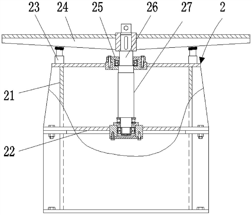
The invention discloses a wire rod flat steel putting device which comprises a base and forming groove wheels. A rotating device comprises second supports, a connecting plate, electric telescopic rods, a second supporting plate, a bearing seat, a rotating shaft and a motor is arranged at the left end of the top of the base, and a supporting sliding block comprising a third supporting plate, ejecting plates, a shaft sleeve, adjusting screws, second threaded plates and first threaded plates is arranged on the top of the rotating device. A stop wheel is fixedly connected to the right end of the top of the base through a third support. By means of the wire rod flat steel putting device, the base, the rotating device, the supporting sliding block, the stop wheel, carrier rollers, guide wheels and the forming groove wheels are arranged, a put wire rod flat steel body can be directly formed, no intermediate link exists, in addition, after one wire rod flat steel body is formed, only the wirerod flat steel body needs to be cut off, then forming of the next wire rod flat steel body can be conducted, continuous work can be achieved, and the production efficiency is improved; and meanwhile the wire rod flat steel putting device is simple in structure, convenient to operate and capable of facilitating application and popularization.

Description

technical field [0001] The invention relates to the technical field of rotary discharging, in particular to a disc round flat steel discharging device. Background technique [0002] Flat steel refers to steel with a width of 12-300mm, a thickness of 3-60mm, a rectangular cross-section and slightly blunt edges. Iron hoops, tools and mechanical parts are used in buildings as structural parts of house frames and escalators. In order to facilitate transportation, flat steel manufacturers usually roll very long flat steel into circular rings. Such flat steel is called Round flat steel, in the process of using the flat steel, it is necessary to use a discharge device to unwind the round flat steel. In the prior art, the discharge device is generally a horizontal discharge. For vertical discharge Occasions, such as vertical stewing flat steel rings, are not applicable, for this reason, we propose a kind of disc round flat steel feeding device. Contents of the invention [0003]...

Claims


Application Information

Patent Timeline
Patent Type & Authority Applications(China)
IPC IPC(8): B21D7/08B21D3/05B21C47/16
CPCB21C47/16B21D3/05B21D7/08
Inventor 崔闻天常根生刘国民聂军秦瑞
Owner XINXING ENERGY EQUIP
Why Eureka
Try Eureka