Electromagnetic locking differential mechanism

A differential and electromagnetic lock technology, applied in the direction of differential transmission, belt/chain/gear, mechanical equipment, etc., can solve problems such as inability to get out of trouble, slipping, and insufficient adhesion

Pending Publication Date: 2020-10-13
台州市阿瑞诗汽车配件有限公司
View PDF0 Cites 3 Cited by
  • Summary
  • Abstract
  • Description
  • Claims
  • Application Information

AI Technical Summary

Problems solved by technology

[0003] However, when the car encounters extremely bad road conditions, such as muddy and very bad roads, due to the function of the differential, one side will The tire o

Method used


Image

  • Electromagnetic locking differential mechanism
  • Electromagnetic locking differential mechanism
  • Electromagnetic locking differential mechanism

Examples


Example Embodiment

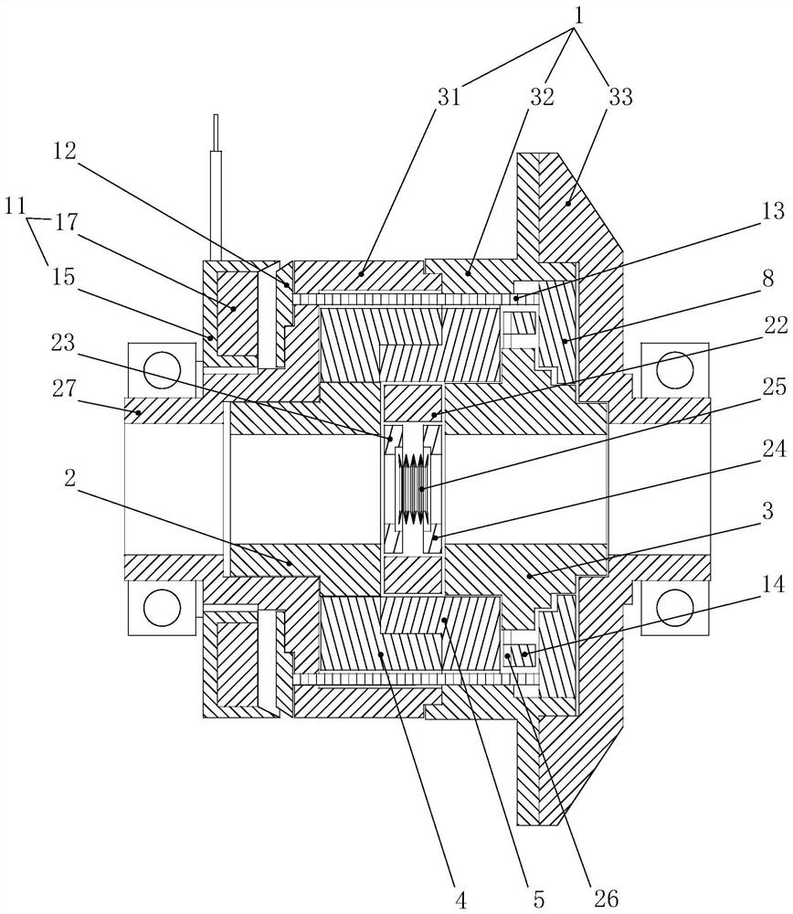
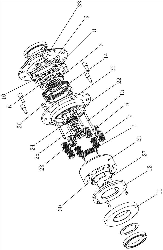
[0026] The present invention will be further described below with specific embodiments, referring to figure 1 -7:

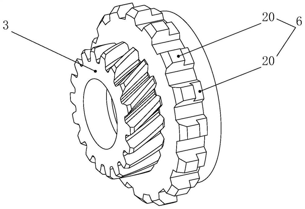
[0027] An electromagnetic locking differential comprises a housing 1 having a cavity, and the cavity is rotatably connected with a front axle helical tooth 2, a rear axle helical tooth 3, a front planetary gear 4 meshing with the front axle helical tooth 2, And the rear planetary gears 5 meshing with the rear axle helical teeth 3, the front planetary gears 4 and the rear planetary gears 5 are in one-to-one correspondence and meshing. Wherein, a set of planetary gear sets are respectively formed between the front axle helical teeth 2 , the front planetary gears 4 and the housing 1 , and between the front axle helical teeth 2 , the front planetary gears 4 and the housing 1 .

[0028] On the side wall of the rear half shaft helical tooth 3 located on the rear side of the rear planetary gear 5, a meshing tooth 1 6 is provided, the inner side wall of the chamber is p...


PUM


Abstract

The invention belongs to the technical field of differential mechanisms, and particularly discloses an electromagnetic locking differential mechanism. The electromagnetic locking differential mechanism comprises a shell body with a cavity, wherein a front half-shaft spiral gear, a rear half-shaft spiral gear, a front planetary gear and a rear planetary gear are rotatably connected into the cavity,a first engaging gear is formed in the rear half-shaft spiral gear, a first straight gear is formed in the cavity, a locking ring is arranged in the cavity, a second straight gear is formed in an outer ring of the locking ring, and a second engaging gear is formed in an inner ring; and an electromagnetic coil is arranged on the front side of the shell body, a suction ring is arranged between theelectromagnetic coil and the shell body, the suction ring is fixedly connected with the front end of a pull rod, the rear end of the pull rod is fixedly connected with the locking ring, and a reset spring is arranged between the locking ring and the rear planetary gear. According to the electromagnetic locking differential mechanism, with the help of a magnetic field generated by the electromagnetic coil being electrified, the suction ring can be subjected to forward magnetic attraction in the magnetic field, thus the locking ring can be driven to move forward through the pull rod, the first engaging gear of the rear half-shaft spiral gear is engaged with the second engaging gear of the locking ring, and the 100% locking of the differential mechanism is achieved.

Description

Technical field: [0001] The invention belongs to the technical field of differentials, in particular to an electromagnetic locking differential. Background technique: [0002] The differential is a device with the functions of power transmission and power distribution. Its function is to allow the axle shafts on both sides to rotate at different speeds when the car encounters a turn, so that the wheels on both sides can drive at unequal distances in the form of pure rolling as much as possible. , Reduce the sliding friction between the tire and the ground, thereby ensuring the safety factor of the driving vehicle and improving the operating life of the reducer. [0003] However, when the car encounters extremely bad road conditions, such as muddy and very bad road surfaces, due to the function of the differential, the tires on one side will slip due to insufficient adhesion to the road surface, and the tires on the other side will slip. Instead, the tires don't turn, leavin...

Claims


Application Information

Patent Timeline
IPC IPC(8): F16H48/06F16H48/24F16H48/34F16H48/40
CPCF16H48/06F16H48/24F16H48/34F16H48/40
Inventor 林江辉张美富
Owner 台州市阿瑞诗汽车配件有限公司
Why Eureka
Try Eureka