An auxiliary fixing device for a railway signal machine
A technology for railway signals and fixtures, which is applied in the direction of supporting machines, mechanical equipment, machines/supports, etc., can solve the problem that the installation of railway signals cannot be automatically and quickly realized.
- Summary
- Abstract
- Description
- Claims
- Application Information
AI Technical Summary
Problems solved by technology
Method used
Image
Examples
specific Embodiment approach 1
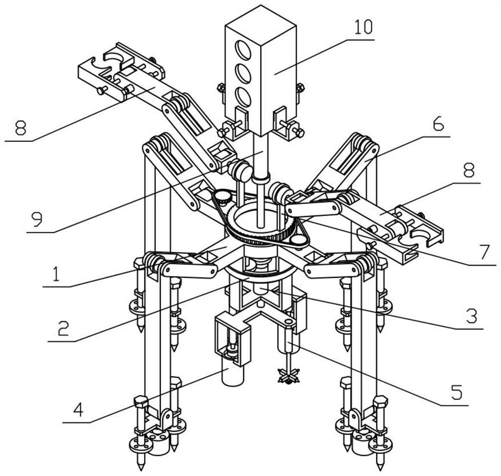
[0036] Combine below Figure 1-12 Description of this embodiment, an auxiliary fixing device for a railway signal machine, including a device bracket 1, a rotating mechanism I2, a lifting mechanism I3, an excavating mechanism 4, a fixing mechanism 5, a positioning arm 6, a rotating mechanism II7, a supporting arm 8, a lifting mechanism Mechanism II9 and railway signal machine 10, the lower end of the device bracket 1 is connected with a rotating mechanism I2, the rotating mechanism I2 is fixedly connected with a lifting mechanism I3, the lifting mechanism I3 is fixedly connected with an excavating mechanism 4, and the lifting mechanism I3 is fixedly connected There are fixing mechanisms 5, four positioning arms 6 are provided, and the four positioning arms 6 are all fixedly connected on the device bracket 1, and the device bracket 1 is connected with a rotating mechanism II 7, and two supporting arms 8 are provided, and the two supporting arms 8 Both are fixedly connected to t...
specific Embodiment approach 2
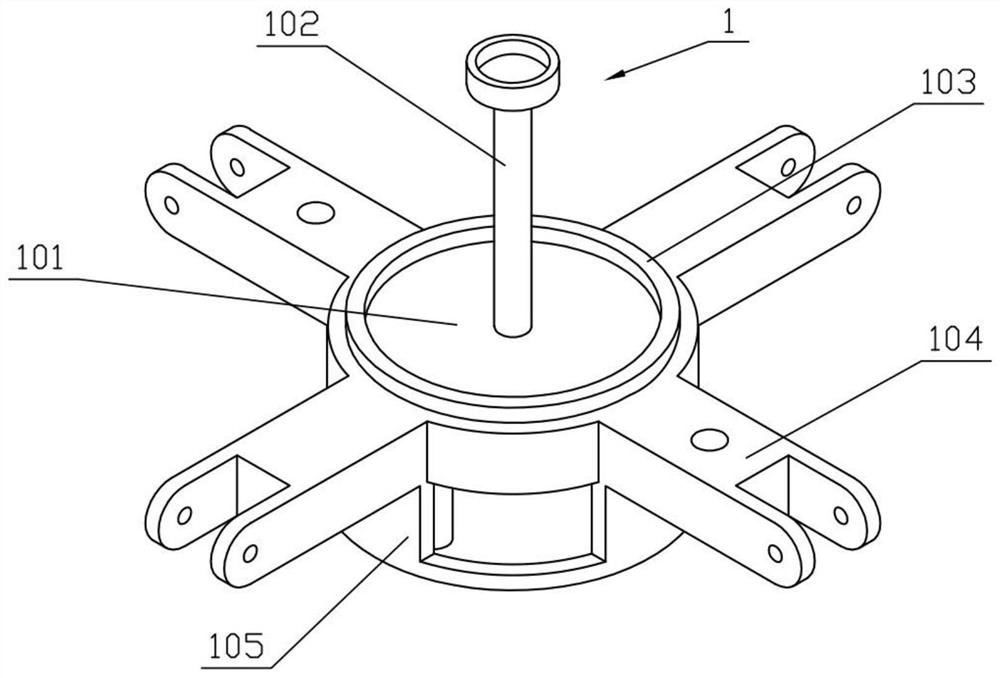
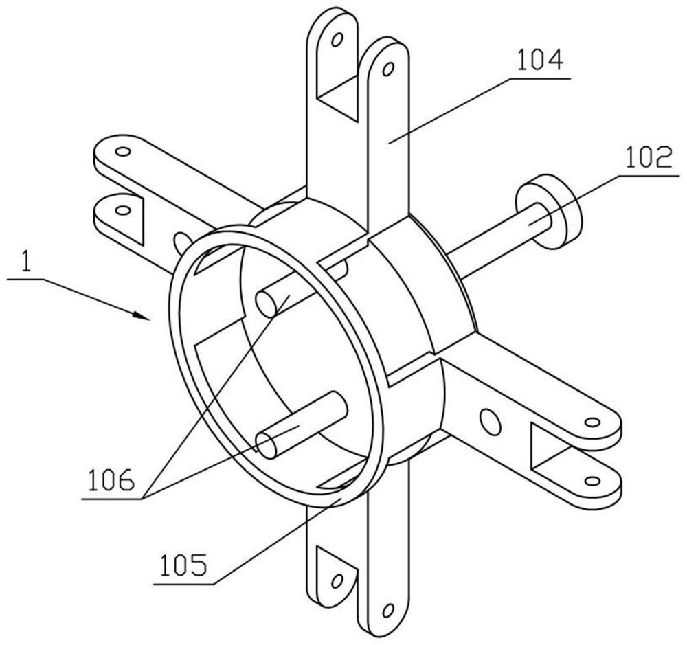
[0038] Combine below Figure 1-12 Describe this embodiment, this embodiment will further explain Embodiment 1, the device bracket 1 includes a mounting ring 101, a supporting column 102, a supporting ring I 103, a hinged frame 104, a supporting ring II 105 and a rotating shaft 106, and the middle part of the mounting ring 101 The support column 102 is fixedly connected, the upper end of the installation ring 101 is fixedly connected with the support ring I 103, the outer circumference of the installation ring 101 is uniformly fixedly connected with four hinged frames 104, the lower end of the installation ring 101 is fixedly connected with the support ring II 105, the installation ring The lower end of 101 is fixedly connected with a rotating shaft 106 .
specific Embodiment approach 3
[0040] Combine below Figure 1-12 This embodiment will be described. This embodiment will further explain the second embodiment. The rotating mechanism I2 includes a rotating motor I201, a planetary gear I202, a rotating ring gear 203, and a turret 204. The rotating motor I201 is fixedly connected to the mounting ring 101. The planetary gear I 202 is rotatably connected to the rotating shaft 106, the output shaft of the rotating motor I 201 is engaged with the planetary gear I 202 for transmission, the planetary gear I 202 is engaged with the rotating ring gear 203 for transmission, and the rotating ring gear 203 is rotatably connected to the support ring II 105, and the rotating ring gear The lower end of 203 is fixedly connected with the turret 204 .
PUM
 Abstract
Description
Claims
Application Information
 - R&D
- Intellectual Property
- Life Sciences
- Materials
- Tech Scout
- Unparalleled Data Quality
- Higher Quality Content
- 60% Fewer Hallucinations
Browse by: Latest US Patents, China's latest patents, Technical Efficacy Thesaurus, Application Domain, Technology Topic, Popular Technical Reports.
© 2025 PatSnap. All rights reserved.Legal|Privacy policy|Modern Slavery Act Transparency Statement|Sitemap|About US| Contact US: help@patsnap.com


