Double-channel fuel nozzle with adjustable valve
A fuel nozzle and adjustable technology, applied in the direction of combustion chamber, combustion method, combustion equipment, etc., can solve the problems of valve performance decline and difficult recovery, and achieve the effect of avoiding pressure bearing performance decline.
- Summary
- Abstract
- Description
- Claims
- Application Information
AI Technical Summary
Problems solved by technology
Method used
Image
Examples
Embodiment 1
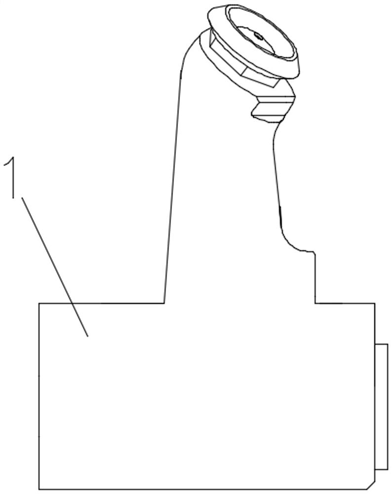
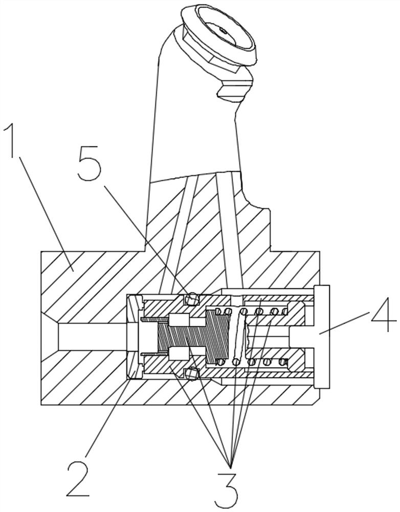
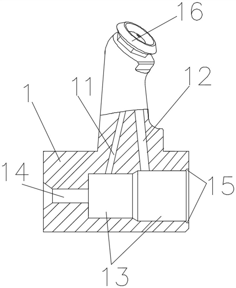
[0034] based on Figure 1-11 As shown, a dual-channel fuel nozzle with an adjustable valve includes a T-shaped nozzle housing 1, an oil separator 2, a valve device 3, and a valve plug 4 for fixing the valve device 3. The T-shaped structure The nozzle housing 1 is provided with an oil inlet hole 14, a valve cylinder 13 and a valve plugging hole 15 sequentially in the horizontal section of the T-shaped structure, and the valve cylinder 13 is sequentially provided with an oil separator 2 and a valve device along the direction of the valve plugging hole 15 3 and the valve plug 4, the valve cylinder 13 includes the main oil cylinder 131 and the auxiliary oil cylinder 132 arranged in sequence along the direction of the valve plugging hole 15, the nozzle housing 1 of the T-shaped structure is in the vertical section of the T-shaped structure and is far away from the T One end of the horizontal section of the shaped structure is provided with a nozzle 16, and the main oil cylinder 131...
Embodiment 2
[0038] Based on Embodiment 1, the valve device 3 includes a valve cylinder body 31, and a movable block 32, a spring 33 and a spring support seat 34 arranged in sequence in the valve cylinder body 31 for opening and closing the oil circuit, the valve cylinder body The end of 31 close to the oil inlet hole 14 is provided with a seal ring groove 311 for inlaying the seal ring 5, and the middle part of the valve cylinder 31 is provided with an oil passage hole b312 for connecting the inner cavity of the valve cylinder body 31 and the inner cavity of the auxiliary oil cylinder 132. One end of the inner surface of the valve cylinder 31 near the valve plug 15 is provided with a section of internal thread 313 that matches the external thread 341 on the spring support seat 34. The oil through hole a321 that passes into oil in 31.
[0039] When the oil pressure is lower than the preset oil pressure, the oil flows to the main oil cylinder 132 through the oil inlet hole 14 through the oi...
Embodiment 3
[0042] Based on Embodiment 2, the two ends of the spring are embedded on the movable block 32 and the spring support seat 34 respectively.
[0043] The side of the oil separator 2 close to the valve device 3 is provided with a plurality of protrusions 21 distributed in an annular array around the center of the oil separator 2 .
[0044] The oil flows into the main oil cylinder 131 through the gap between the protrusions 21 on the diverter plate 2 .
[0045] The valve plug 4 is welded to the valve plug hole 15 on the nozzle housing 1 .
[0046] In the present invention, a bi-directionally adjustable valve device 3 is provided in the valve cylinder 13 of the nozzle housing 1, so as to avoid the pressure-bearing performance of the valve falling after a long time of use, and the need to replace the spring or adjust the gasket again, which is troublesome to operate. time-consuming problem.
PUM
 Abstract
Description
Claims
Application Information
 - R&D
- Intellectual Property
- Life Sciences
- Materials
- Tech Scout
- Unparalleled Data Quality
- Higher Quality Content
- 60% Fewer Hallucinations
Browse by: Latest US Patents, China's latest patents, Technical Efficacy Thesaurus, Application Domain, Technology Topic, Popular Technical Reports.
© 2025 PatSnap. All rights reserved.Legal|Privacy policy|Modern Slavery Act Transparency Statement|Sitemap|About US| Contact US: help@patsnap.com


