Novel heat exchanger core

A heat exchanger, core technology, applied in the direction of heat exchanger conduit, heat exchanger type, indirect heat exchanger, etc., can solve the problems of reducing the service life of heat exchanger, blockage, flow channel scaling, etc. The effect of heat exchange demand

Pending Publication Date: 2018-03-09
AEROSPACE HIWING HARBIN TITANIUM IND
View PDF5 Cites 6 Cited by
  • Summary
  • Abstract
  • Description
  • Claims
  • Application Information

AI Technical Summary

Problems solved by technology

Due to the different cleanliness of the fluid working medium used in heat exchangers, when using low cleanliness working fluid, it often occurs due to fouling in the flow channel, or blockage due to excessive particle diameter in the working fluid, reducing the service life of the heat exchanger

Method used


Image

  • Novel heat exchanger core
  • Novel heat exchanger core
  • Novel heat exchanger core

Examples


Embodiment 1

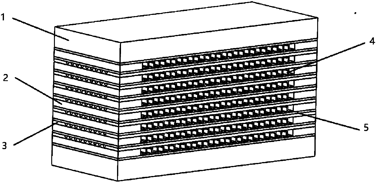
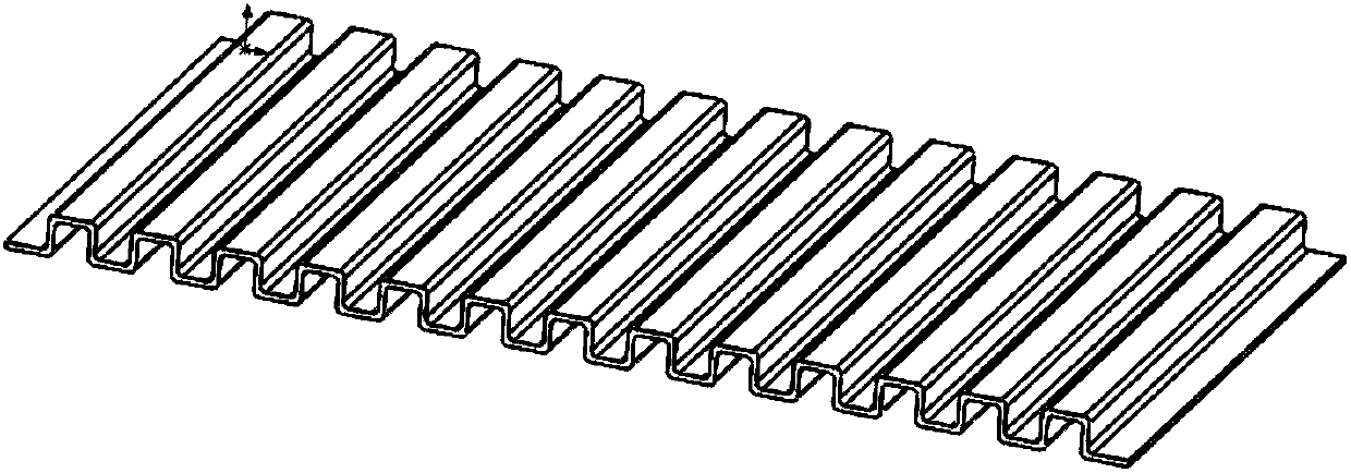
[0042] combine Figure 1-7 , this embodiment provides a new type of heat exchanger core, including two cover plates 1, baffle plates 2, etched plates 3, formed plates 4 and partitions 5; the formed plates 4 and partitions 5 constitute A structural unit A; the structural unit A and the etched sheet 3 are stacked alternately between the two cover plates 1; the non-etched surface of the etched sheet 3 is in contact with the forming sheet 4; the etched surface of the etched sheet 3 is in contact with the corresponding The partitions 5 of the adjacent structural unit A are butted against each other; two baffles 2 are provided at both ends of each of the forming plates 4; a partition 5 is also provided between the cover plate 1 and the etching plate 3; the cover plate 1 and A partition 5 is also arranged between the forming plates 4; the cover plate 1, the baffle plate 2, the etching plate 3, the forming plate 4 and the dividing plate 5 are processed into a cuboid; the forming plate...

Embodiment 2

[0046] The difference between this embodiment and Embodiment 1 is: the cover plate 1, the baffle plate 2, the etching plate 3, the forming plate 4 and the partition plate 5 are processed into a cuboid; the forming plate 4 is rectangular, and the inlet and outlet of the flow channel are set On the wide side of the rectangle; the etching plate 3 is rectangular, and the inlet and outlet of the flow channel are arranged on the long side of the rectangle.

Embodiment 3

[0048] The difference between this embodiment and Embodiment 1 is that: the cover plate 1, the baffle plate 2, the etched plate 3, the forming plate 4 and the partition 5 are processed into a cube; the forming plate 4 is a square and the etched plate 3 It is a square; the inlets and outlets of the flow channels of the etched sheet 3 and the shaped sheet 4 are arranged on different sides of the square.

[0049] In this embodiment, when the cover plate is in contact with the forming plate, a spacer can be added between the two; when the cover plate is in contact with the etched surface of the etched plate, a spacer can be added between the two; When the non-etched sides of the plates are in contact, a spacer can optionally be added between the two.

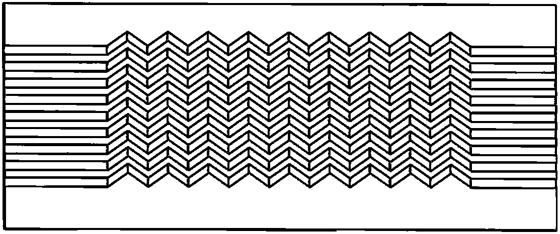
[0050] In this embodiment, the etched plate 3 is to process different forms of flow channels on the plate by chemical etching. The flow channels can be straight channels or zigzag channels. The flow channel inlet and outlet of the e...


PUM


Abstract

The invention discloses a novel heat exchanger core and belongs to the technical field of mechanical design. The heat exchanger core includes two cover plates, an etching plate piece, a forming platepiece and partition plates. The forming plate piece and the partition plate form a structural unit. The structural unit and the etching plate piece are alternately overlaid between the two cover plates, the non-etched surface of the etching plate piece is in butt joint with the forming plate piece, the etched surface of the etching plate piece is in butt joint with the adjacent structural unit, the partition plates are arranged between the cover plates and the etching plate piece, and the partition plates are arranged between the cover plates and the forming plate piece. The cover plates, theetching plate piece, the forming plate piece and the partition plates are machined into a whole. The novel heat exchanger core integrates the characteristics of a microchannel heat exchanger and a plate heat exchanger and can meet the use conditions that the working medium cleanliness is not high, and the novel heat exchanger core is particularly suitable for natural gas cooling processes of an offshore work platform.

Description

technical field [0001] The invention relates to a novel heat exchanger core and belongs to the technical field of heat exchange design. Background technique [0002] At present, micro-channel heat exchangers have been widely used in ships, automobiles, air-conditioning and other industries. Due to their small size and light weight, micro-channel heat exchangers have become an important new direction of heat exchanger research and development. Due to the different cleanliness of the fluid working medium used in heat exchangers, when using low cleanliness working fluid, it often occurs due to fouling in the flow channel, or blockage due to excessive particle diameter in the working fluid, reducing the the service life of the heat exchanger. Contents of the invention [0003] In order to solve the deficiencies of the prior art, the present invention provides a novel heat exchanger core, and the adopted technical scheme is as follows: [0004] The purpose of the present inve...

Claims


Application Information

Patent Timeline
Patent Type & Authority Applications(China)
IPC IPC(8): F28D9/00F28F3/00F28F19/00F28D9/02F28F3/12
CPCF28D9/0062F28D9/02F28F3/005F28F3/12F28F19/00F28F2210/08F28F2260/02
Inventor 韩芳明李雪梅刘莹肖波刘俊秀崔庆龙王文博
Owner AEROSPACE HIWING HARBIN TITANIUM IND
Why Eureka
Try Eureka