T-fitting

A technology of three-way pipe and main pipe, which is applied in the direction of pipe connection arrangement, pipe/pipe joint/pipe fitting, household components, etc., to achieve the effect of improving pressure resistance

Inactive Publication Date: 2013-04-03
GEORG FISCHER ROHRLEITUNGSSYST
View PDF2 Cites 6 Cited by
  • Summary
  • Abstract
  • Description
  • Claims
  • Application Information

AI Technical Summary

Problems solved by technology

[0008] Such an approach is associated with the disadvantage of increased material consumption by re-machining the hollow rod and additional labor involved in subsequent reinforcement assembly

Method used


Image

  • T-fitting
  • T-fitting
  • T-fitting

Examples


Embodiment Construction

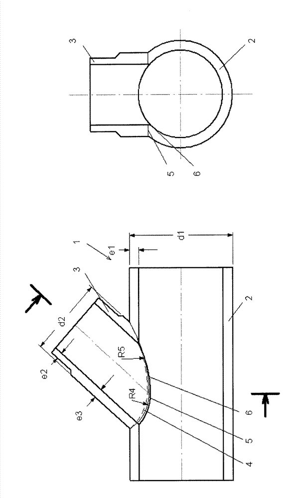
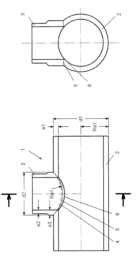
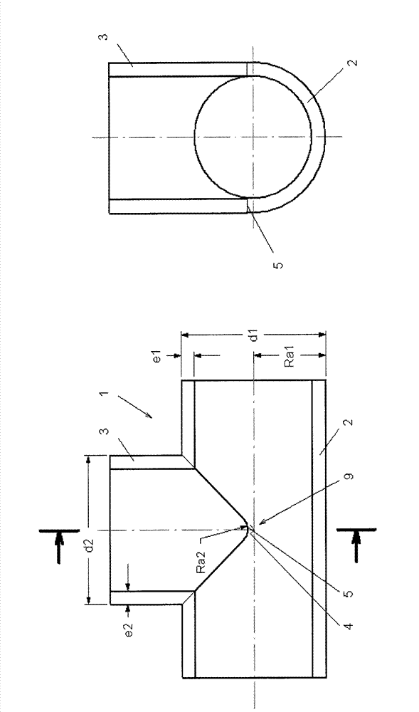
[0046] figure 1 A welded tee 1 is shown with a branch 3 extending at a 90° angle to the main pipe 2 or joined perpendicularly to the main pipe 2 . The diameter d2 of the branch pipe 3 does not match the diameter d1 of the main pipe 2 . Thus, in figure 1 It is shown that tubes 2, 3 having different diameters d1, d2 are welded together. In order to form a good weld, it is advantageous that the wall thicknesses e1 , e3 are approximately equal in the region of the weld, resulting in the same joint pressure conditions. Furthermore, the widened wall thickness leads to increased strength. It is therefore advantageous to make the wall thickness of the pipes to be joined together or to adapt it, for example by increasing the wall thickness e3 in the branch pipe 3, as figure 1 shown. The theoretical line of intersection 4 that would appear when joining the two pipes 2, 3 together is at figure 1 is shown by dashed line 4. The approximate intersecting line 5 is obtained from the pr...


PUM


Abstract

The invention relates to a T-fitting and a method of producing a welded pipe tee from thermoplastic, wherein the pipes to be joined together are welded along their approximating intersection curve.

Description

technical field [0001] The present invention relates to a thermoplastic welded tee and a method for making the same. Background technique [0002] Tees are used in piping systems to create pipe outlets or branches. Thermoplastics are increasingly used in piping construction for reasons of weight and corrosion. Fluids such as gas, water, waste water or indeed chemicals are preferably conveyed in such piping. [0003] Various methods for producing plastic tees are known from the prior art. [0004] Typically, the tee is manufactured using injection molding. This method is especially suitable for piping systems or tees that do not exceed a certain size. The reason for this is that, on the one hand, the method is not economically feasible unless a certain number of units of tees are manufactured, which is rarely the case for larger sizes; , also reaches the feasibility frontier. Injection molding is suitable for large sizes only to a limited extent. [0005] US 5,551,733 ...

Claims


Application Information

Patent Timeline
Patent Type & Authority Applications(China)
IPC IPC(8): F16L47/32B29C65/18
CPCF16L47/32B29L2031/246B29C65/20B29C66/114B29C66/116B29C66/1162B29C66/301B29C66/5224B29C66/52241B29C66/71B29C66/7392B29C66/81411B29C66/81451B29C66/73921Y10T156/1066B29K2077/00B29K2023/12B29K2023/06B29K2023/18B29K2027/16B29K2023/04B29K2023/10
Inventor J.韦梅林格
Owner GEORG FISCHER ROHRLEITUNGSSYST
Why Eureka
Try Eureka