Touch panel and electronic equipment

A touch panel and touch electrode technology, which is applied in the fields of electrical digital data processing, instruments, calculations, etc., can solve problems such as user experience needs to be improved, and achieve the effect of improving the touch experience

Pending Publication Date: 2020-10-16
FU TAI HUA IND SHENZHEN +1
View PDF7 Cites 1 Cited by
  • Summary
  • Abstract
  • Description
  • Claims
  • Application Information

AI Technical Summary

Problems solved by technology

However, the above-mentioned touch panel structure can only realize

Method used


Image

  • Touch panel and electronic equipment
  • Touch panel and electronic equipment
  • Touch panel and electronic equipment

Examples


Example Embodiment

[0020] Example 1

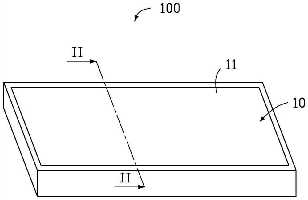
[0021] see figure 1 , the electronic device 100 provided in this embodiment includes a touch panel 10 . The electronic device 100 may be various types of electronic devices with touch functions, such as a touch display device, a mobile terminal, a smart home appliance, and the like. This embodiment is described by taking the electronic device 100 as an example of a touch display device.

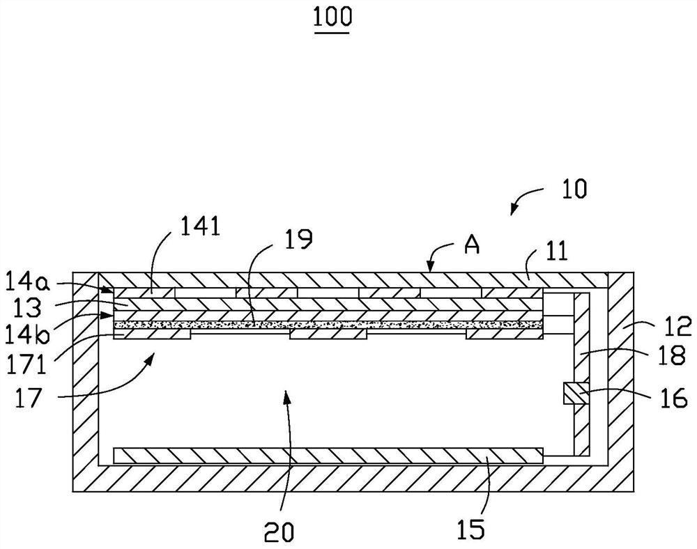
[0022] see figure 2 , the touch panel 10 includes a cover plate 11 and an outer frame 12, the cover plate 11 and the outer frame 12 together form a closed receiving space 20, the cover plate 11 has a surface A that is not received in the receiving space 20, wherein, The surface A is used to receive the touch operation of the user. For example, if the user performs a touch operation with a finger, the surface A is the touch surface of the finger.
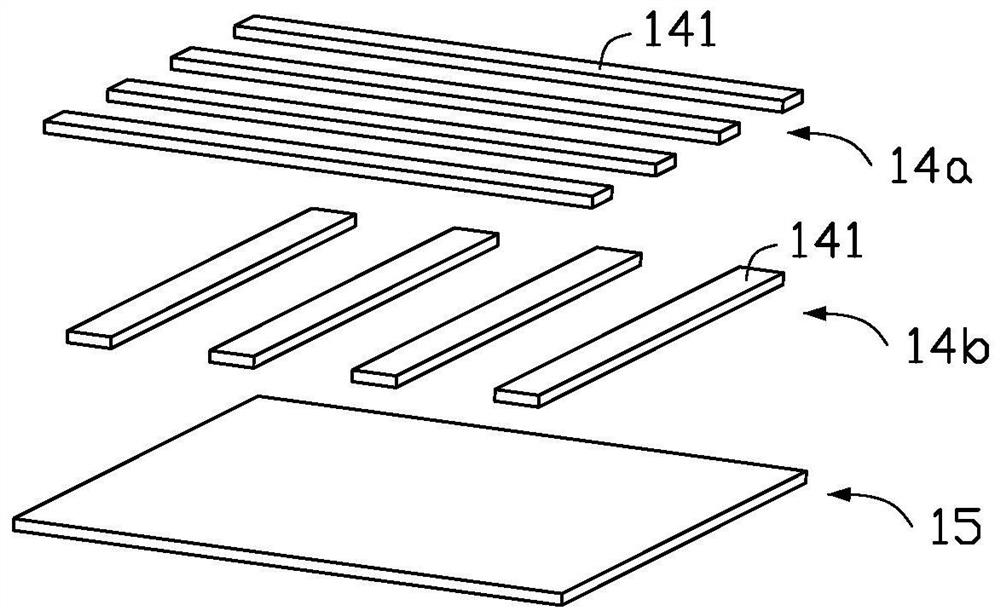
[0023] please continue figure 2 , the touch panel 10 further includes a substrate 13 disposed in the receiving space 20 ,...

Example Embodiment

[0036] Embodiment 2

[0037] see Figure 5 The electronic device 200 provided in this embodiment includes a touch panel 30 . The difference from the first embodiment is that the placement positions of the vibration structure 17 and the circuit board 18 of the touch panel 30 are different. Only the different parts are described in detail below.

[0038] In this embodiment, the cover plate 31 and the outer frame 12 are jointly enclosed to form a closed receiving space 40 , and the cover plate 31 has a surface B that is not received in the receiving space 40 , wherein the surface B is used to receive a user's touch operation For example, when the user performs a touch operation with a finger, the surface B is the touch surface of the finger.

[0039] please continue Figure 5 The touch panel 30 further includes the circuit board 18 disposed in the receiving space 40 , the first touch electrode group 14 a disposed on the side of the circuit board 18 close to the cover plate 31 ...


PUM


Abstract

The invention provides a touch panel, which comprises: a plurality of touch electrodes used for obtaining touch sensing signals generated by touch operation at the current moment; the force sensing electrode that is arranged opposite to the touch control electrode, an initial capacitance value exists between the force sensing electrode and the touch control electrode, and when the touch control operation occurs, the initial capacitance value changes; the processor that is electrically connected with the touch electrodes and the force sensing electrodes, and is used for detecting the occurrenceposition of the touch operation according to the touch sensing signal and generating a control signal according to the variation of the initial capacitance value; and the vibration structure that iselectrically connected with the processor and is used for vibrating according to the control signal when the touch operation occurs. The invention further provides electronic equipment.

Description

technical field [0001] The present invention relates to the field of touch control, in particular to a touch panel and electronic equipment including the touch panel. Background technique [0002] A touch panel, also known as a touch screen, is a command input device, which is widely used in various smart devices as a convenient way of human-computer interaction. [0003] Existing touch panels mainly include resistive touch panels, capacitive touch panels, infrared touch panels, and surface acoustic wave touch panels. Among them, capacitive touch panels have low cost, long life and high sensitivity. Advantages, therefore, have been widely used in electronic devices such as mobile communication terminals, portable media players, digital cameras, and tablet computers. Generally speaking, in the prior art, the method for the capacitive touch panel to detect the user's touch position is to calculate the coordinate position of the touch by using the change of capacitance when th...

Claims


Application Information

Patent Timeline
IPC IPC(8): G06F3/041G06F3/044
CPCG06F3/0416G06F3/044G06F3/016G06F3/0446G06F3/0447G06F3/0448
Inventor 黄仁义简源宏
Owner FU TAI HUA IND SHENZHEN
Why Eureka
Try Eureka