
Bending device and bending machine

A technology of bending device and bending part, applied in the field of bending machine, can solve the problems of incomplete support, interference of side and cutting surface, etc.

Pending Publication Date: 2020-10-20
SANY HEAVY EQUIP
View PDF0 Cites 0 Cited by
  • Summary
  • Abstract
  • Description
  • Claims
  • Application Information

AI Technical Summary

Problems solved by technology

[0002] At present, after the traditional continuous miner cuts the coal seam, it needs to use steel mesh and anchor bolts for support. When performing automated unmanned operations, if a steel mesh with the same width as the roadway is used, due to the irregularity of the cutting surface It will cause interference between the two sides of the steel mesh and the cutting surface. If a steel mesh narrower than the width of the roadway is used for support, gaps will inevitably be left on both sides of the roadway, and the support is incomplete. Usually, two pieces of steel mesh are used for support. The support operation is carried out after the steel mesh is superimposed. At the same time, the edge of the steel mesh is bent before the support and fixed on the top and side of the roadway to ensure the integrity of the support. Therefore, it is urgent to develop a convenient on-site Bending device used

Method used


Image

  • Bending device and bending machine
  • Bending device and bending machine
  • Bending device and bending machine

Examples


Embodiment Construction

[0035] In order to understand the above-mentioned purpose, features and advantages of the present invention more clearly, the present invention will be further described in detail below in conjunction with the accompanying drawings and specific embodiments. It should be noted that, in the case of no conflict, the embodiments of the present application and the features in the embodiments can be combined with each other.

[0036] In the following description, many specific details are set forth in order to fully understand the present invention. However, the present invention can also be implemented in other ways different from those described here. Therefore, the protection scope of the present invention is not limited by the specific details disclosed below. EXAMPLE LIMITATIONS.

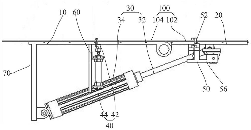
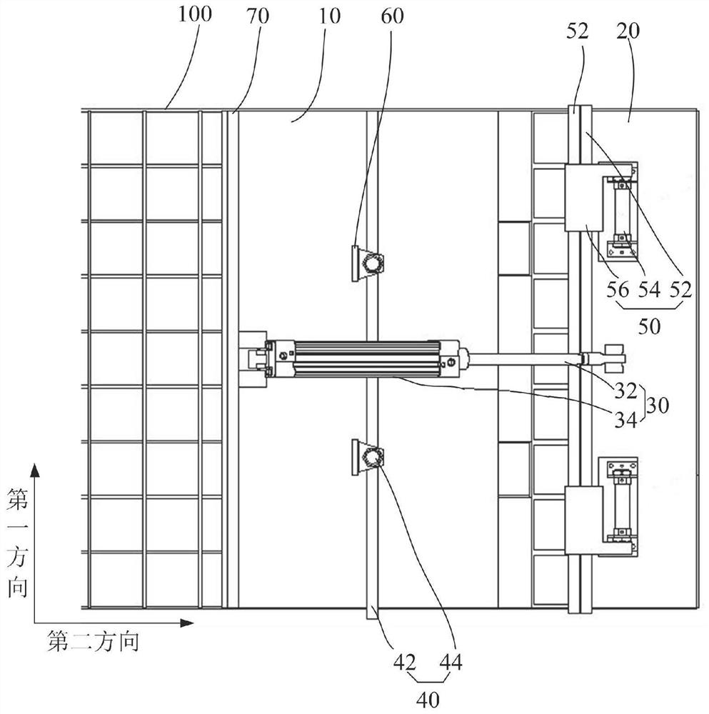
[0037] It should be noted that the first direction in this application refers to figure 2 The vertical direction in the application, the second direction in this application refers to figure 2 in...


PUM


Abstract

The invention provides a bending device and a bending machine. The bending device comprises a fixing plate, an overturning plate, a driving piece, a limiting assembly and a clamping assembly, whereinthe overturning plate is pivotally connected with the fixing plate, the driving piece can drive the overturning plate to rotate relative to the fixing plate, the clamping assembly is used for clampinga to-be-bent part to enable the to-be-bent part to rotate together along with the overturning plate, and the limiting assembly is used for limiting a non-bent part to rotate together along with the to-be-bent part. According to the technical scheme, under the driving effect of the driving piece, the overturning plate drives the to-be-bent part to rotate together, and the non-bent part cannot rotate together with the to-be-bent part under the limiting effect of the limiting assembly, so that the to-be-bent part and the non-bent part rotate relatively, and the bending function of the bending device on the to-be-bent part is achieved.

Description

technical field [0001] The invention relates to the technical field of bending machines, in particular, to a bending device and a bending machine. Background technique [0002] At present, after the traditional continuous miner cuts the coal seam, it needs to use steel mesh and bolts for support. When performing automated unmanned operations, if a steel mesh equal to the width of the roadway is used, due to the irregularity of the cutting surface It will cause interference between the two sides of the steel mesh and the cutting surface. If a steel mesh narrower than the width of the roadway is used for support, gaps will inevitably be left on both sides of the roadway, and the support is incomplete. Usually, two pieces of steel mesh are used for support. The support operation is carried out after the steel mesh is stacked. At the same time, the edge of the steel mesh is bent before the support and fixed on the top and side of the roadway to ensure the integrity of the suppor...

Claims


Application Information

Patent Timeline
IPC IPC(8): B21D11/00B21D11/22B21D43/00
CPCB21D11/00B21D11/22B21D43/003
Inventor 柳枫刘青松
Owner SANY HEAVY EQUIP
Learn More